Sany Crawler Hydraulic Excavator SY245H SY265C Repair Manual
- Download this document, you need 1605 Gallons
Sany Crawler Hydraulic Excavator SY245H SY265C Repair Manual
Size: 70.3 MB
Format: PDF
Brand: Sany
Language: English
Type of Machine: Crawler Hydraulic Excavator
Type of Manual: Repair Manual
Model: SY245H SY265C
Number of Pages: 825 Pages
Content:
1 Foreword And Introduction
1.1 Introduction
1.2 Terminology Note For Maintenance Standard
1.3 Treatment Of Electrical And Hydraulic Components
1.3.1 Treatment Of Electrical And Hydraulic Components
1.3.2 Precautions For Treatment Of Hydraulic Components
1.4 Pipe Connector
1.4.1 Pipe Connector
1.4.2 Type Of Pipe Connector
1.4.3 Tightening Torque Of Pipe Connector
1.4.4 Connection Of O-Ring
1.5 Table Of Standard Tightening Torque
1.6 Bolt Type
1.7 Bolt Tightening Sequence
1.8 Maintenance Of Split Flange
1.8.1 Maintenance Of Split Flange
1.8.2 Table Of Tightening Torques Of Split Flange Bolts
1.9 Conversion Table
2 Safety
2.1 Instructions For Safety Decals
2.1.1 Summary
2.1.2 Safety Signal Terms
2.1.3 Other Signal Terms
2.2 General Precautions
2.2.1 General Precautions
2.2.2 Safety Rules
2.2.3 Keep Working Area Tidy
2.2.4 Fluid Storage
2.2.5 Part Washing
2.2.6 Hydraulic Excavator Cleaning
2.2.7 Decent Clothing
2.2.8 Personal Protective Equipment (Ppe)
2.2.9 Correct Use Of Tools
2.2.10 Fire Extinguisher And Emergency Exit
2.2.11 Emergency Exit And Emergency Hammer In Cab
2.3 Preparations Before Maintenance
2.3.1 Preparations Before Working
2.3.2 Warning Sign Plate
2.3.3 Self-Preparation
2.4 Precautions For Maintenance
2.4.1 Work During Engine Running
2.4.2 Dismantling Accessories Of Hydraulic Excavator
2.4.3 Working Under Hydraulic Excavator
2.4.4 Adding Or Replacing Fluid
2.4.5 Parts Alignment
2.4.6 When A Hammer Is Used
2.4.7 When Compressed Air Is Used
2.4.8 Welding
2.4.9 Spring For Track Tension
2.4.10 Safe Operation For High Pressure Hoses
2.4.11 Be Careful When You Work With High-Pressure Fluid
2.4.12 Be Careful When You Work With Hot Coolant
2.4.13 Hvac Group
2.4.14 Electrical Safety
2.4.15 Switching Power Off
2.4.16 Battery Operation
2.4.17 Accumulator
2.4.18 Reducing Fire And Explosion Risks
2.4.19 Proper Disposal For Waste
2.5 Miscellaneous
2.5.1 Precautions For Hoisting And Signaling
2.5.2 Precautions For Using Mobile Crane
2.5.3 Precautions For Using Bridge Crane
2.5.4 Selection Of Wire Ropes
3 Technical Specifications
3.1 Specified Dimension Figures
3.1.1 Dimension
3.1.2 Working Range
3.2 Technical Specifications
3.3weight Table
3.4 Capacity Table
3.5 Engine Oil, Fuel And Coolant
3.6 Engine Graph (Mitsubishi Model D06frc-Taa)
4 Structure And Function
4.1 Power System
4.1.1 Engine
4.1.2 Radiator And Intercooler
4.1.3 Fuel System
4.1.4 Schematic Diagram Of The Lubrication System
4.2 Power Train
4.2.1 Powertrain
4.2.2 Travel Reducer Assembly (Tm40vd)
4.2.3 Reducer (Doosan)
4.2.4swing Reducer Mechanism
4.2.5swing Bearing
4.3 Undercarriage And Frame
4.3.1 Track Frame And Tension Mechanism
4.3.2idler
4.3.3carrier Roller
4.3.4track Roller
4.3.5 Crawler
4.3.6 Three-Teeth Track Shoe
4.4 Hydraulic System, Part 1
4.4.1 Layout Of Hydraulic Parts
4.4.2hydraulic Tank And filter
4.4.3 Hydraulic Pump
4.4.4pilot Pump
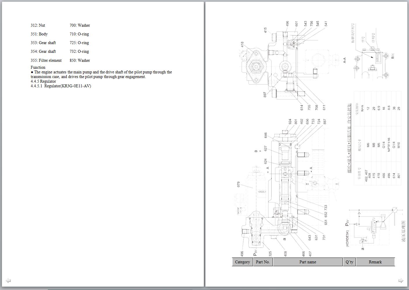
4.4.5 Regulator
4.4.5.1regulator(Kr3g-0e11-Av)
4.4.5.2 Adjustment Of The Regulator
4.5 Hydraulic System, Part 2
4.5.1control Valve Kmx15rb
4.5.2hydraulic Circuit Diagram
4.5.3 Operating Principle
4.5.3.1 When Spool Is In Neutral Position
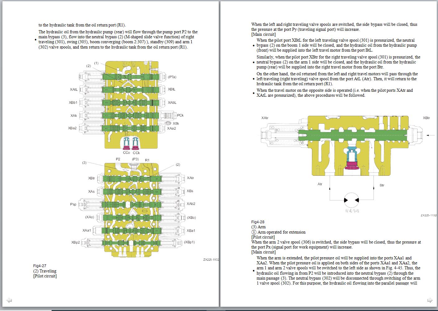
4.5.3.2 Travel
4.5.3.3arm
4.5.3.4 Boom
4.5.3.5 Bucket
4.5.3.6 Swing
4.5.3.7 Option
4.5.3.8 Travel Straight
4.5.3.9 Lock Valve Function
4.5.3.10 Main Relief Valve Function
4.5.3.11 Port Relief Valve Function
4.5.4 Sectional Diagram
4.6 Hydraulic System, Part 3
4.6.1swing Motor
4.6.2 Swing Retention Brake
4.6.3 Relief Valve Portion
4.6.4 Reverse Prevention Valve
4.6.4.1 Damping Valve
4.6.5 Central Swivel Joint
4.6.6 Travel Motor
4.6.6.1 Travel Motor
4.6.6.2 Actions Of All Basic Elements Of The Travel Motor
4.6.7 Control System
4.6.8 Pilot Valve
4.6.8.1 Pilot Valve
4.6.8.2 Travel Pilot Valve
4.6.9 Solenoid Valve
4.6.10 Accumulator
4.6.11 Pilot Oil filter
4.6.12 Pump Oil Pressure Sensor
4.6.13 Hydraulic Cylinder
4.7 Work Equipment
4.7.1 Work Equipment
4.7.2 Arm
Size
4.7.3 Bucket
Size
4.8 Air Conditioning System
4.8.1 Hvac Group
4.8.2 Layout Of A/C Elements
4.8.3 A/C Control Panel
4.8.4 Schematic Circuit Diagram
4.8.5 Working Principles Of A/C
4.8.5.1 Schematic Diagram Of Refrigeration Cycle
4.8.5.2 Schematic Diagram Of Heating Cycle
4.8.6 Compressor
4.8.7 Clutch
4.8.8 Condenser
4.8.9 Expansion Valve
4.8.10 Evaporator
4.8.11 Receiver Tank
4.8.12 Pressure Switch
4.8.13 Fresh Air Sensor
4.8.14refrigerant
4.8.15 Compressor Oil
4.9 Engine Control
4.9.1engine Control
4.9.2 System Components
4.9.2.1 System Components
4.9.2.2controller
4.10 Electrical Control System
4.10.1control Function
4.10.2machine Control System Diagram
4.10.3engine - Pump Combination Control Function
4.10.4 Pump Control Function
4.10.4.1pump Control Function
4.10.4.2 Electrical Positive Flow Control
4.10.4.3 Constant Power Control
4.10.5 Valve Control Function
4.10.5.1 Valve Control Function
4.10.5.2 Bucket fl Ow Control
4.10.5.3 Swing Priority Control
4.10.6 Traveling Dual-Speed Control
4.10.7 Engine Warm-Up/Overheating Alarm
4.10.7.1engine Warm-Up/Overheating Alarm
4.10.7.2 Engine Preheating
4.10.7.3 Engine Overheating Alarm
4.10.8 Engine Oil Under–Pressure Alarm
4.10.9auto Deceleration/Acceleration Control
4.10.10engine Speed Calibration Function
4.10.11 System Parts
4.10.11.1 System Parts
4.10.11.2 Pilot Pressure Sensor
4.10.11.3 Fuel Level Sensor
4.10.11.4 Fuel Level Sensor
4.11 Display System
4.11.1monitoring System
4.11.2display Appearance
4.11.3introduction To The Display Function
4.11.4function And Operation Of The Display
5 Standard Values Of Components
5.1 Table Of Standard Values Of Engine Related Components
5.2 Table Of Standard Values Of Body Related Components
6 Test And Adjustment
6.1 Engine Speed Inspection
6.2 Exhaust Smoke Measurement
6.3 Valve Clearance Adjustment
6.4 Compression Pressure Measurement
6.5 Oil Pressure Measurement
6.6 Adjustment Of Engine Speed Sensor
6.7 Inspection And Adjustment Of A/C Compressor Belt Tensioner
6.8 Measurement Of Swing Bearing Clearance
6.9 Inspection And Adjustment Of Track Tensioner
6.10 Inspection And Adjustment Of Hydraulic Oil In The Work Equipment, Swing And Travel Hydraulic Lines
6.11 Inspection And Adjustment Of Oil Pressure In Control Oil Line
6.12 Measuring The Output Pressure Of Solenoid Valve
6.13 Measuring The Output Pressure Of Pilot Valve
6.14 Adjustment Of Work Equipment And Swing Pilot Valve
6.15 Inspection Of The Drift Of Hydraulic Cylinder For Work Equipment
6.16 Release Of Residual Pressure From Hydraulic Lines
6.17 Leakage Measurement
6.18 Bleeding Air From Each System
6.19 Test Method And Standard For Engine Body Sensor
6.20 Bleeding Air From The Fuel Filter
6.21 Belt Check And Tension Adjustment
7 Fault Diagnosis And Troubleshooting
7.1 Precautions During Fault Diagnosis
7.2 Inspection Before Fault Diagnosis
7.3 Fault Diagnosis Category And Steps
7.4 Fault-Find Out The Symptoms And Fault Diagnosis Numbers
7.5 Connector Position Table And System Circuit Diagram
7.5.1 Connector Position Table And System Circuit Diagram
7.5.2 Connector Position Diagram
7.5.3 System Electric Element Circuit Diagram (Cab Circuit)
7.5.4 Electric Control System Circuit Diagram (Engine Circuit)
7.5.5 Electric Control System Circuit Diagram (Sensor And Solenoid Valve Circuit)
7.5.6 Swp Connector
7.5.7 A/Amp Connector
7.5.8 Dt Connector
7.6 Fault Diagnosis When The Current Dtc Is Displayed
7.6.1 Information Of The Fault Diagnosis Table
7.6.2 Electrical System Service Code E111 (Controller Storage Fault (From))
7.6.3 Electrical System Service Code E015 (Power Voltage Abnormality)
7.6.4 Electrical System Service Code E116 (Controller Internal Temperature Abnormality)
7.6.5 Electrical System Service Code E017 (Sensor 5 V Power Output Abnormality)
7.6.6 Electrical System Service Code E118(Abnormal Communication Between The Controller And Display)
7.6.7 Electrical System Service Code E320 (Front Pump Output Pressure Abnormality)
7.6.8 Electrical System Service Code E321 (Rear Pump Output Pressure Abnormality)
7.6.9 Electrical System Service Code E322 (Arm Digging Pilot Pressure Abnormality)
7.6.10 Electrical System Service Code E323 (Arm Unloading Pilot Pressure Abnormality)
7.6.11 Electrical System Service Code E324
7.6.12 Electrical System Service Code E325
7.6.13 Electrical System Service Code E326
7.6.14 Electrical System Service Code E327
7.6.15 Electrical System Service Code E328 (Swing Pilot Pressure Abnormality)
7.6.16 Electrical System Service Code E329 (Left Traveling Pilot Pressure Abnormality)
7.6.17 Electrical System Service Code E330 (Right Traveling Pilot Pressure Abnormality)
7.6.18 Electrical System Service Code E231 (Fuel Control Knob Setting Voltage Abnormality)
7.6.19 Electrical System Service Code E237 (Hydraulic Oil Temperature Abnormality)
7.6.20 Electrical System Service Code E450 (Front Pump Proportional Solenoid Coil Current Abnormality A)
7.6.21 Electrical System Service Code E450 (Front Pump Proportional Solenoid Coil Current Abnormality B)
7.6.22 Electrical System Service Code E451 (Rear Pump Proportional Solenoid Coil Current Abnormality A)
7.6.23 Electrical System Service Code E451 (Rear Pump Proportional Solenoid Coil Current Abnormality B)
7.6.24 Electrical System Service Code E453 (Bucket Connection Proportional Solenoid Coil Current Abnormality A)
7.6.25 Electrical System Service Code E453 (Bucket Connection Proportional Solenoid Coil Current Abnormality B)
7.6.26 Electrical System Service Code E460 (Power Voltage Abnormality)
7.7 Fault Diagnosis Of Electrical System (E Category)
7.7.1 Information Of The Fault Diagnosis Table
7.7.2 E-1 The Engine Cannot Be Started
7.7.3 E-3 The Complete Vehicle Can't Be Powered Off
7.7.4 E-4 It Runs Idly Automatically And Doesn’t Work
7.7.5 E-6 No Equipment Works
7.7.6 E-7 The Boom Lifting Is Slow And Powerless
7.7.7 E-8 The Arm Movement Is Slow And Powerless
7.7.8 E-9 The Bucket Movement Is Slow And Powerless
7.7.9 E-10 The Traveling Is Slow And Powerless
7.7.10 E-11 The Display Is Blank
7.7.11 E-12 The Display Has No Display
7.7.12 E-13 The High/Low Traveling Speed Is Disabled
7.7.13 E-15 The Display Of Fuel Level Is Inaccurate
7.7.14 E-16 The Wiper Doesn’t Work
7.7.15 E-17 The Display Of Arm Digging Pilot Pressure Is Inaccurate
7.7.16 E-18 The Display Of Arm Unloading Pilot Pressure Is Inaccurate
7.7.17 E-19 The Display Of Boom Lifting Pilot Pressure Is Inaccurate
7.7.18 E-20 The Display Of Boom Drop Pilot Pressure Is Inaccurate
7.7.19 E-21 The Display Of Bucket Digging Pilot Pressure Is Inaccurate
7.7.20 E-22 The Display Of Bucket Unloading Pilot Pressure Is Inaccurate
7.7.21 E-23 The Display Of Swing Pilot Pressure Is Inaccurate
7.7.22 E-24 The Display Of Left Traveling Pilot Pressure Is Inaccurate
7.7.23 E-25 The Display Of Right Traveling Pilot Pressure Is Inaccurate
7.8 Fault Diagnosis Of Hydraulic And Mechanical System (H Fault
7.8.1 Table Of Hydraulic And Mechanical System
7.8.2 Information Of The Fault Diagnosis Table
7.8.3 H-1 The Work Equipment Moves Slowly, Or It Has Low Traveling And Rotation Speed
7.8.4 H-2 The Engine Speed Significantly Drops Or Engine Stalls
7.8.5 H-3 The Work Equipment Has No Movement, And Traveling Or Swing Function Is Disabled
7.8.6 H-4 The Hydraulic Pump Has Unusual Noise
7.8.7 H-5 It Runs Idly Automatically And Doesn’t Work
7.8.8 H-6 The Boom Moves Slowly
7.8.9 H-7 The Arm Moves Slowly
7.8.10 H-8 The Bucket Moves Slowly
7.8.11 H-9 The Single Cylinder Of The Work Equipment Has No Movement
7.8.12 H-10 The Cylinder Drift Of The Work Equipment Is Too Large
7.8.13 H-11 The Work Equipment Moves Slowly
7.8.14 H-12 Other Work Equipment Moves When A Single Oil Line Has An Overflow
7.8.15 H-13 The Traveling Speed Drops Obviously During Swing+Traveling
7.8.16 H-14 The Machine Has Off-Tracking During Traveling
7.8.17 H-15 The Machine Travels At Low Speed
7.8.18 H-16 The Machine Is Hard To Turn Or Powerless
7.8.19 H-17 The Traveling Speed Cannot Be Shifted
7.8.20 H-18 It Cannot Travel (Only On One Side)
7.8.21 H-19 The Machine Cannot Swing
7.8.22 H-20 It Has Low Swing Acceleration Performance Or Low Swing Speed
7.8.23 H-21 The Overrun Is Too Large When Swing Stops
7.8.24 H-22 The Impact Is Too Large When Swing Stops
7.8.25 H-23 The Unusual Noise Is Too Loud When Swing Stops
7.8.26 H-24 The Natural Drift During Swing Is Too Large
8 Disassembly And Reassembly
8.1 Precautions During Operation
8.2 Disassembly And Reassembly Of Engine Body
8.3 Removal And Installation Of Radiator Assembly
8.4 Removal And Installation Of Engine And Hydraulic Pump Assembly
8.5 Removal And Installation Of Final Drive Assembly
8.6 Disassembly And Reassembly Of Final Drive Assembly
8.7 Removal And Installation Of Swing Motor And Swing Mechanism Assembly
8.8 Disassembly And Reassembly Of Swing Motor And Swing Mechanism Assembly
8.9 Disassembly And Reassembly Of Idler Assembly
8.10 Removal And Installation Of Sprocket
8.11 Removal And Installation Of Track Assembly
8.12 Removal And Installation Of Swing Bearing Assembly
8.13 Removal And Installation Of Turntable Assembly
8.14 Removal And Installation Of Center Swivel Joint Assembly
8.15 Disassembly And Reassembly Of Center Swivel Joint Assembly
8.16 Removal And Installation Of Hydraulic Tank Assembly
8.17 Removal And Installation Of Control Valve Assembly
8.18 Removal And Installation Of Hydraulic Pump Assembly
8.19 Removal And Installation Of Oil Seal In The Input Shaft Of Hydraulic Pump
8.20 Disassembly And Reassembly Of Pilot Valve Assembly Of Work Equipment
8.21 Disassembly And Reassembly Of Travel Pilot Valve Assembly
8.22 Disassembly And Reassembly Of Hydraulic Cylinder Assembly
8.23 Removal And Installation Of Work Equipment Assembly
8.24 Removal And Installation Of Hvac Assembly
8.25 Removal And Installation Of Counterweight Assembly
8.26 Removal And Installation Of Cab Assembly
8.27 Removal And Installation Of Cab Windows
8.28 Removal And Installation Of Front Window Assembly
8.29 Removal And Installation Of Display Screen
8.30 Removal And Installation Of Controller Assembly
8.31 Installation And Removal Of Radio
8.32 Battery
8.33 Ignition Key Switch
8.34 Fuse Box
8.35 Wiper
8.36 Sensor
8.37 Relay
8.38 Terminal Insertion And Removal
9 Hydraulic And Electrical Diagrams
9.1 Hydraulic Lines Diagram
9.2 Electrical Diagram Of Hvac Group
9.3 Electrical Diagram Of Control Switch
9.4 Electrical Diagram Of Display Screen
9.5 Electrical Diagram Of Cab
9.6 Electrical Diagram Of Body
Size: 70.3 MB
Format: PDF
Brand: Sany
Language: English
Type of Machine: Crawler Hydraulic Excavator
Type of Manual: Repair Manual
Model: SY245H SY265C
Number of Pages: 825 Pages
Content:
1 Foreword And Introduction
1.1 Introduction
1.2 Terminology Note For Maintenance Standard
1.3 Treatment Of Electrical And Hydraulic Components
1.3.1 Treatment Of Electrical And Hydraulic Components
1.3.2 Precautions For Treatment Of Hydraulic Components
1.4 Pipe Connector
1.4.1 Pipe Connector
1.4.2 Type Of Pipe Connector
1.4.3 Tightening Torque Of Pipe Connector
1.4.4 Connection Of O-Ring
1.5 Table Of Standard Tightening Torque
1.6 Bolt Type
1.7 Bolt Tightening Sequence
1.8 Maintenance Of Split Flange
1.8.1 Maintenance Of Split Flange
1.8.2 Table Of Tightening Torques Of Split Flange Bolts
1.9 Conversion Table
2 Safety
2.1 Instructions For Safety Decals
2.1.1 Summary
2.1.2 Safety Signal Terms
2.1.3 Other Signal Terms
2.2 General Precautions
2.2.1 General Precautions
2.2.2 Safety Rules
2.2.3 Keep Working Area Tidy
2.2.4 Fluid Storage
2.2.5 Part Washing
2.2.6 Hydraulic Excavator Cleaning
2.2.7 Decent Clothing
2.2.8 Personal Protective Equipment (Ppe)
2.2.9 Correct Use Of Tools
2.2.10 Fire Extinguisher And Emergency Exit
2.2.11 Emergency Exit And Emergency Hammer In Cab
2.3 Preparations Before Maintenance
2.3.1 Preparations Before Working
2.3.2 Warning Sign Plate
2.3.3 Self-Preparation
2.4 Precautions For Maintenance
2.4.1 Work During Engine Running
2.4.2 Dismantling Accessories Of Hydraulic Excavator
2.4.3 Working Under Hydraulic Excavator
2.4.4 Adding Or Replacing Fluid
2.4.5 Parts Alignment
2.4.6 When A Hammer Is Used
2.4.7 When Compressed Air Is Used
2.4.8 Welding
2.4.9 Spring For Track Tension
2.4.10 Safe Operation For High Pressure Hoses
2.4.11 Be Careful When You Work With High-Pressure Fluid
2.4.12 Be Careful When You Work With Hot Coolant
2.4.13 Hvac Group
2.4.14 Electrical Safety
2.4.15 Switching Power Off
2.4.16 Battery Operation
2.4.17 Accumulator
2.4.18 Reducing Fire And Explosion Risks
2.4.19 Proper Disposal For Waste
2.5 Miscellaneous
2.5.1 Precautions For Hoisting And Signaling
2.5.2 Precautions For Using Mobile Crane
2.5.3 Precautions For Using Bridge Crane
2.5.4 Selection Of Wire Ropes
3 Technical Specifications
3.1 Specified Dimension Figures
3.1.1 Dimension
3.1.2 Working Range
3.2 Technical Specifications
3.3weight Table
3.4 Capacity Table
3.5 Engine Oil, Fuel And Coolant
3.6 Engine Graph (Mitsubishi Model D06frc-Taa)
4 Structure And Function
4.1 Power System
4.1.1 Engine
4.1.2 Radiator And Intercooler
4.1.3 Fuel System
4.1.4 Schematic Diagram Of The Lubrication System
4.2 Power Train
4.2.1 Powertrain
4.2.2 Travel Reducer Assembly (Tm40vd)
4.2.3 Reducer (Doosan)
4.2.4swing Reducer Mechanism
4.2.5swing Bearing
4.3 Undercarriage And Frame
4.3.1 Track Frame And Tension Mechanism
4.3.2idler
4.3.3carrier Roller
4.3.4track Roller
4.3.5 Crawler
4.3.6 Three-Teeth Track Shoe
4.4 Hydraulic System, Part 1
4.4.1 Layout Of Hydraulic Parts
4.4.2hydraulic Tank And filter
4.4.3 Hydraulic Pump
4.4.4pilot Pump
4.4.5 Regulator
4.4.5.1regulator(Kr3g-0e11-Av)
4.4.5.2 Adjustment Of The Regulator
4.5 Hydraulic System, Part 2
4.5.1control Valve Kmx15rb
4.5.2hydraulic Circuit Diagram
4.5.3 Operating Principle
4.5.3.1 When Spool Is In Neutral Position
4.5.3.2 Travel
4.5.3.3arm
4.5.3.4 Boom
4.5.3.5 Bucket
4.5.3.6 Swing
4.5.3.7 Option
4.5.3.8 Travel Straight
4.5.3.9 Lock Valve Function
4.5.3.10 Main Relief Valve Function
4.5.3.11 Port Relief Valve Function
4.5.4 Sectional Diagram
4.6 Hydraulic System, Part 3
4.6.1swing Motor
4.6.2 Swing Retention Brake
4.6.3 Relief Valve Portion
4.6.4 Reverse Prevention Valve
4.6.4.1 Damping Valve
4.6.5 Central Swivel Joint
4.6.6 Travel Motor
4.6.6.1 Travel Motor
4.6.6.2 Actions Of All Basic Elements Of The Travel Motor
4.6.7 Control System
4.6.8 Pilot Valve
4.6.8.1 Pilot Valve
4.6.8.2 Travel Pilot Valve
4.6.9 Solenoid Valve
4.6.10 Accumulator
4.6.11 Pilot Oil filter
4.6.12 Pump Oil Pressure Sensor
4.6.13 Hydraulic Cylinder
4.7 Work Equipment
4.7.1 Work Equipment
4.7.2 Arm
Size
4.7.3 Bucket
Size
4.8 Air Conditioning System
4.8.1 Hvac Group
4.8.2 Layout Of A/C Elements
4.8.3 A/C Control Panel
4.8.4 Schematic Circuit Diagram
4.8.5 Working Principles Of A/C
4.8.5.1 Schematic Diagram Of Refrigeration Cycle
4.8.5.2 Schematic Diagram Of Heating Cycle
4.8.6 Compressor
4.8.7 Clutch
4.8.8 Condenser
4.8.9 Expansion Valve
4.8.10 Evaporator
4.8.11 Receiver Tank
4.8.12 Pressure Switch
4.8.13 Fresh Air Sensor
4.8.14refrigerant
4.8.15 Compressor Oil
4.9 Engine Control
4.9.1engine Control
4.9.2 System Components
4.9.2.1 System Components
4.9.2.2controller
4.10 Electrical Control System
4.10.1control Function
4.10.2machine Control System Diagram
4.10.3engine - Pump Combination Control Function
4.10.4 Pump Control Function
4.10.4.1pump Control Function
4.10.4.2 Electrical Positive Flow Control
4.10.4.3 Constant Power Control
4.10.5 Valve Control Function
4.10.5.1 Valve Control Function
4.10.5.2 Bucket fl Ow Control
4.10.5.3 Swing Priority Control
4.10.6 Traveling Dual-Speed Control
4.10.7 Engine Warm-Up/Overheating Alarm
4.10.7.1engine Warm-Up/Overheating Alarm
4.10.7.2 Engine Preheating
4.10.7.3 Engine Overheating Alarm
4.10.8 Engine Oil Under–Pressure Alarm
4.10.9auto Deceleration/Acceleration Control
4.10.10engine Speed Calibration Function
4.10.11 System Parts
4.10.11.1 System Parts
4.10.11.2 Pilot Pressure Sensor
4.10.11.3 Fuel Level Sensor
4.10.11.4 Fuel Level Sensor
4.11 Display System
4.11.1monitoring System
4.11.2display Appearance
4.11.3introduction To The Display Function
4.11.4function And Operation Of The Display
5 Standard Values Of Components
5.1 Table Of Standard Values Of Engine Related Components
5.2 Table Of Standard Values Of Body Related Components
6 Test And Adjustment
6.1 Engine Speed Inspection
6.2 Exhaust Smoke Measurement
6.3 Valve Clearance Adjustment
6.4 Compression Pressure Measurement
6.5 Oil Pressure Measurement
6.6 Adjustment Of Engine Speed Sensor
6.7 Inspection And Adjustment Of A/C Compressor Belt Tensioner
6.8 Measurement Of Swing Bearing Clearance
6.9 Inspection And Adjustment Of Track Tensioner
6.10 Inspection And Adjustment Of Hydraulic Oil In The Work Equipment, Swing And Travel Hydraulic Lines
6.11 Inspection And Adjustment Of Oil Pressure In Control Oil Line
6.12 Measuring The Output Pressure Of Solenoid Valve
6.13 Measuring The Output Pressure Of Pilot Valve
6.14 Adjustment Of Work Equipment And Swing Pilot Valve
6.15 Inspection Of The Drift Of Hydraulic Cylinder For Work Equipment
6.16 Release Of Residual Pressure From Hydraulic Lines
6.17 Leakage Measurement
6.18 Bleeding Air From Each System
6.19 Test Method And Standard For Engine Body Sensor
6.20 Bleeding Air From The Fuel Filter
6.21 Belt Check And Tension Adjustment
7 Fault Diagnosis And Troubleshooting
7.1 Precautions During Fault Diagnosis
7.2 Inspection Before Fault Diagnosis
7.3 Fault Diagnosis Category And Steps
7.4 Fault-Find Out The Symptoms And Fault Diagnosis Numbers
7.5 Connector Position Table And System Circuit Diagram
7.5.1 Connector Position Table And System Circuit Diagram
7.5.2 Connector Position Diagram
7.5.3 System Electric Element Circuit Diagram (Cab Circuit)
7.5.4 Electric Control System Circuit Diagram (Engine Circuit)
7.5.5 Electric Control System Circuit Diagram (Sensor And Solenoid Valve Circuit)
7.5.6 Swp Connector
7.5.7 A/Amp Connector
7.5.8 Dt Connector
7.6 Fault Diagnosis When The Current Dtc Is Displayed
7.6.1 Information Of The Fault Diagnosis Table
7.6.2 Electrical System Service Code E111 (Controller Storage Fault (From))
7.6.3 Electrical System Service Code E015 (Power Voltage Abnormality)
7.6.4 Electrical System Service Code E116 (Controller Internal Temperature Abnormality)
7.6.5 Electrical System Service Code E017 (Sensor 5 V Power Output Abnormality)
7.6.6 Electrical System Service Code E118(Abnormal Communication Between The Controller And Display)
7.6.7 Electrical System Service Code E320 (Front Pump Output Pressure Abnormality)
7.6.8 Electrical System Service Code E321 (Rear Pump Output Pressure Abnormality)
7.6.9 Electrical System Service Code E322 (Arm Digging Pilot Pressure Abnormality)
7.6.10 Electrical System Service Code E323 (Arm Unloading Pilot Pressure Abnormality)
7.6.11 Electrical System Service Code E324
7.6.12 Electrical System Service Code E325
7.6.13 Electrical System Service Code E326
7.6.14 Electrical System Service Code E327
7.6.15 Electrical System Service Code E328 (Swing Pilot Pressure Abnormality)
7.6.16 Electrical System Service Code E329 (Left Traveling Pilot Pressure Abnormality)
7.6.17 Electrical System Service Code E330 (Right Traveling Pilot Pressure Abnormality)
7.6.18 Electrical System Service Code E231 (Fuel Control Knob Setting Voltage Abnormality)
7.6.19 Electrical System Service Code E237 (Hydraulic Oil Temperature Abnormality)
7.6.20 Electrical System Service Code E450 (Front Pump Proportional Solenoid Coil Current Abnormality A)
7.6.21 Electrical System Service Code E450 (Front Pump Proportional Solenoid Coil Current Abnormality B)
7.6.22 Electrical System Service Code E451 (Rear Pump Proportional Solenoid Coil Current Abnormality A)
7.6.23 Electrical System Service Code E451 (Rear Pump Proportional Solenoid Coil Current Abnormality B)
7.6.24 Electrical System Service Code E453 (Bucket Connection Proportional Solenoid Coil Current Abnormality A)
7.6.25 Electrical System Service Code E453 (Bucket Connection Proportional Solenoid Coil Current Abnormality B)
7.6.26 Electrical System Service Code E460 (Power Voltage Abnormality)
7.7 Fault Diagnosis Of Electrical System (E Category)
7.7.1 Information Of The Fault Diagnosis Table
7.7.2 E-1 The Engine Cannot Be Started
7.7.3 E-3 The Complete Vehicle Can't Be Powered Off
7.7.4 E-4 It Runs Idly Automatically And Doesn’t Work
7.7.5 E-6 No Equipment Works
7.7.6 E-7 The Boom Lifting Is Slow And Powerless
7.7.7 E-8 The Arm Movement Is Slow And Powerless
7.7.8 E-9 The Bucket Movement Is Slow And Powerless
7.7.9 E-10 The Traveling Is Slow And Powerless
7.7.10 E-11 The Display Is Blank
7.7.11 E-12 The Display Has No Display
7.7.12 E-13 The High/Low Traveling Speed Is Disabled
7.7.13 E-15 The Display Of Fuel Level Is Inaccurate
7.7.14 E-16 The Wiper Doesn’t Work
7.7.15 E-17 The Display Of Arm Digging Pilot Pressure Is Inaccurate
7.7.16 E-18 The Display Of Arm Unloading Pilot Pressure Is Inaccurate
7.7.17 E-19 The Display Of Boom Lifting Pilot Pressure Is Inaccurate
7.7.18 E-20 The Display Of Boom Drop Pilot Pressure Is Inaccurate
7.7.19 E-21 The Display Of Bucket Digging Pilot Pressure Is Inaccurate
7.7.20 E-22 The Display Of Bucket Unloading Pilot Pressure Is Inaccurate
7.7.21 E-23 The Display Of Swing Pilot Pressure Is Inaccurate
7.7.22 E-24 The Display Of Left Traveling Pilot Pressure Is Inaccurate
7.7.23 E-25 The Display Of Right Traveling Pilot Pressure Is Inaccurate
7.8 Fault Diagnosis Of Hydraulic And Mechanical System (H Fault
7.8.1 Table Of Hydraulic And Mechanical System
7.8.2 Information Of The Fault Diagnosis Table
7.8.3 H-1 The Work Equipment Moves Slowly, Or It Has Low Traveling And Rotation Speed
7.8.4 H-2 The Engine Speed Significantly Drops Or Engine Stalls
7.8.5 H-3 The Work Equipment Has No Movement, And Traveling Or Swing Function Is Disabled
7.8.6 H-4 The Hydraulic Pump Has Unusual Noise
7.8.7 H-5 It Runs Idly Automatically And Doesn’t Work
7.8.8 H-6 The Boom Moves Slowly
7.8.9 H-7 The Arm Moves Slowly
7.8.10 H-8 The Bucket Moves Slowly
7.8.11 H-9 The Single Cylinder Of The Work Equipment Has No Movement
7.8.12 H-10 The Cylinder Drift Of The Work Equipment Is Too Large
7.8.13 H-11 The Work Equipment Moves Slowly
7.8.14 H-12 Other Work Equipment Moves When A Single Oil Line Has An Overflow
7.8.15 H-13 The Traveling Speed Drops Obviously During Swing+Traveling
7.8.16 H-14 The Machine Has Off-Tracking During Traveling
7.8.17 H-15 The Machine Travels At Low Speed
7.8.18 H-16 The Machine Is Hard To Turn Or Powerless
7.8.19 H-17 The Traveling Speed Cannot Be Shifted
7.8.20 H-18 It Cannot Travel (Only On One Side)
7.8.21 H-19 The Machine Cannot Swing
7.8.22 H-20 It Has Low Swing Acceleration Performance Or Low Swing Speed
7.8.23 H-21 The Overrun Is Too Large When Swing Stops
7.8.24 H-22 The Impact Is Too Large When Swing Stops
7.8.25 H-23 The Unusual Noise Is Too Loud When Swing Stops
7.8.26 H-24 The Natural Drift During Swing Is Too Large
8 Disassembly And Reassembly
8.1 Precautions During Operation
8.2 Disassembly And Reassembly Of Engine Body
8.3 Removal And Installation Of Radiator Assembly
8.4 Removal And Installation Of Engine And Hydraulic Pump Assembly
8.5 Removal And Installation Of Final Drive Assembly
8.6 Disassembly And Reassembly Of Final Drive Assembly
8.7 Removal And Installation Of Swing Motor And Swing Mechanism Assembly
8.8 Disassembly And Reassembly Of Swing Motor And Swing Mechanism Assembly
8.9 Disassembly And Reassembly Of Idler Assembly
8.10 Removal And Installation Of Sprocket
8.11 Removal And Installation Of Track Assembly
8.12 Removal And Installation Of Swing Bearing Assembly
8.13 Removal And Installation Of Turntable Assembly
8.14 Removal And Installation Of Center Swivel Joint Assembly
8.15 Disassembly And Reassembly Of Center Swivel Joint Assembly
8.16 Removal And Installation Of Hydraulic Tank Assembly
8.17 Removal And Installation Of Control Valve Assembly
8.18 Removal And Installation Of Hydraulic Pump Assembly
8.19 Removal And Installation Of Oil Seal In The Input Shaft Of Hydraulic Pump
8.20 Disassembly And Reassembly Of Pilot Valve Assembly Of Work Equipment
8.21 Disassembly And Reassembly Of Travel Pilot Valve Assembly
8.22 Disassembly And Reassembly Of Hydraulic Cylinder Assembly
8.23 Removal And Installation Of Work Equipment Assembly
8.24 Removal And Installation Of Hvac Assembly
8.25 Removal And Installation Of Counterweight Assembly
8.26 Removal And Installation Of Cab Assembly
8.27 Removal And Installation Of Cab Windows
8.28 Removal And Installation Of Front Window Assembly
8.29 Removal And Installation Of Display Screen
8.30 Removal And Installation Of Controller Assembly
8.31 Installation And Removal Of Radio
8.32 Battery
8.33 Ignition Key Switch
8.34 Fuse Box
8.35 Wiper
8.36 Sensor
8.37 Relay
8.38 Terminal Insertion And Removal
9 Hydraulic And Electrical Diagrams
9.1 Hydraulic Lines Diagram
9.2 Electrical Diagram Of Hvac Group
9.3 Electrical Diagram Of Control Switch
9.4 Electrical Diagram Of Display Screen
9.5 Electrical Diagram Of Cab
9.6 Electrical Diagram Of Body
Last edited:
More the random threads same category:
- Sany Container Reach Stacker RSC45C2 Operation & Maintenance Manual
- SANY Hydraulic Crawler Crane SCC500E COMPLETE MANUAL
- Sany Hydraulic Excavator SY215C9M2K Parts Book
- Sany Container Reach Stacker Safety, Operation & Maintenance Manual
- Sany Body Container Reach Stacker SRSC45C2 Parts Book
- Sany SY205-215C9M2K Electrical Schematics
- SANY Crawler Hydraulic Excavator SY215C Shop Manual
- Sany SY65C-SY135C-8 Electric Hydraulic Schematics
- Sany SCC500E-R1 Crawler Crane Assembly Part Book
- SANY SCC8500 500-ton crawler crane offers multiple configurations
- SANY SY230C8E Electrical Schematics
- Sany Rough Terrain Crane SRC865XL Parts Book
- Sany QY50C Truck Crane Parts Book
- Earthdrill SANY SR220C hydraulic diaphram
- Sany SY200C1-Electrical Schematics