- Gallons
- 288,393
[Linkbelt] Linkbelt Excavator 250X4 and 250X4 LF Service Manual WLSM2507-11LX
- Download this document, you need 2725 Gallons
Linkbelt Excavator 250X4 and 250X4 LF Service Manual WLSM2507-11LX
Size: 113 MB
Format: PDF
Language: English
Brand: Link-Belt
Type of Machine: Excavator
Type of Document: Service Manual
Model: Link-Belt 250X4 Hydraulic Excavator, Link-Belt 250X4 LF Hydraulic Excavator,
Number of Pages: 2228 Pages
Contents:
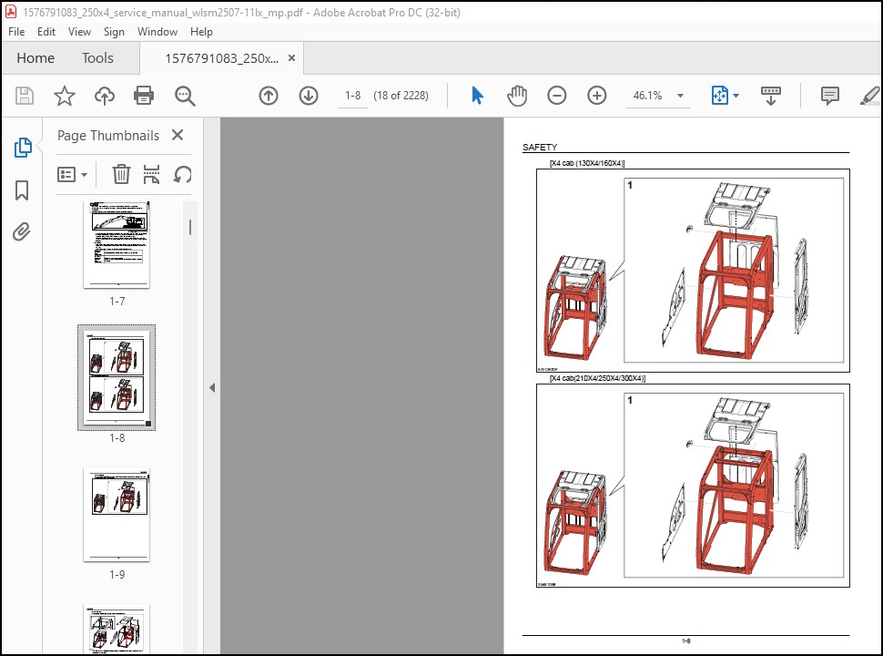
SAFETY
Safety, general information and standard torque data
General Information
Standard Torque Data For Cap Screws And Nuts
Protection of Electric/Electronics System During Charging or Welding
A LOWER
Main Equipment Table
Main Equipment Structure and Operation Explanation
Port Diagram
Basic Functions
Removal and Installation of Track
Removal and Installation of Roller
Removal and Installation of Drive Sprocket
Removal and Installation of Take-up Roller
Assembly and Disassembly of Take-up Roller
Removal and Installation of Grease Cylinder
Assembly and Disassembly of Tension Shock Absorber
Removal and Installation of Center Joint
Assembly and Disassembly of Center Joint
Removal and Installation of Travel Motor
Assembly and Disassembly of Travel Motor
Maintenance Standards
Pressure Measurement and Adjustment Procedures
Drain Volume Measurement Procedures
Air Bleed Procedure
B C SWING UNIT, COUNTERWEIGHT
Main Equipment Table
Main Equipment Structure and Operation Explanation
Port Diagram
Basic Functions
Removal and Installation of Swing Unit
Assembly and Disassembly of Swing Motor
Assembly and Disassembly of Swing Unit
Assembly and Disassembly of Swing Reduction Gear
Removal and Installation of Counterweight
Pressure Measurement and Adjustment Procedures
Drain Volume Measurement Procedures
Air Bleed Procedure
H ENGINE
Main Equipment Table
Basic Functions
Main Data
Function, Structure, Operation
Function, structure, operation (SCR)
SCR Control System Inspection
Explanation of SCR Operation
Diagnosis for Each Symptom
Diagnosis for Each Symptom
Functional Inspection
Removal and Installation of Engine Assembly
Removal and Installation of Fuel Cooler, Engine Intercooler, Radiator, and Oil Cooler
Removal and Installation of Turbo Charger
Removal and Installation of EGR Valve (if equipped)
Removal and Installation of Engine Hood
Removal and Installation of SCR
Removal and installation of Silicon Controlled Rectifier Catalyst
Removal and Installation of Cylinder Head Cover
Removal and Installation of Cylinder Block
Lubrication System
Cooling System
Induction System
Exhaust System
Aux Emission Control Devices System
Removal and Installation of Exhaust Manifold
Removal and Installation of Fuel Tank
Removal and Installation of Urea Pump
Removal and Installation of Urea Solution Tank
Removal and Installation of Fuel Supply Pump
Removal and Installation of Common Rail Assembly
Removal and Installation of Injector
Removal and installation of Idle Gear
Removal and installation of Inlet Cover
Removal and installation of Crankshaft
Removal and installation of Piston
Removal and installation of Camshaft
Removal and installation of Flywheel
Removal and installation of Crankshaft Front Oil Seal
Removal and installation of Crankshaft Rear Oil Seal
Removal and installation of Rocker Arm Shaft
Removal and installation of Valve Spring
Removal and installation of Valve Stem Oil Seal
Removal and installation of Front Cover
Removal and installation of Intake Throttle Valve
Removal and Installation of Starter Motor
Removal and Installation of Alternator
Removal and Installation of Glow Plug
Removal and Installation of Suction Control Valve
Removal and installation of Fuel Filter
Removal and installation of Relief Valve
Removal and installation of Fuel Filter Element
Removal and Installation of Fuel filter pressure
Removal and Installation of Engine coolant temperature sensor
Removal and Installation of CKP sensor
Removal and Installation of CMP sensor
Removal and Installation of Oil pressure sensor
Removal and installation of Pressure Sensor/Boost Temperature Sensor
Removal and Installation of IMT sensor
Removal and installation of Charge Air Cooler Temperature Sensor 1
Sampling Procedure
Removal and Installation of Exhaust gas temperature sensor
Removal and installation of EGR Gas Temperature Sensor 1
Removal and installation of EGR Gas Temperature Sensor 2
Removal and installation of NOx Sensor
Removal and Installation of Exhaust gas temperature sensor 3
Removal and installation of DEF Sensor
Engine-related Diagnostic Trouble Code List
Engine-side Trouble
Data Reference Values
J HYDRAULIC EQUIPMENT (PUMP, OPERATION SYSTEM VALVE)
Main Equipment Table
Basic Functions
Port Diagram
Hydraulic Pump
Control Valve
5 Stack Solenoid Valve Operation Explanation
Upper Pilot Valve (remote control valve)
Travel Pilot Valve (remote control valve)
Cushion Valve
Selector Valve (2-way)
Direction Valve (3-direction)
6 Stack Proportional Valve (Pilot)
Electromagnetic Relief Valve
Removal and Installation of Hydraulic Tank
Removal and Installation of Hydraulic Pump
Removal and Installation of Pump coupling
Removal and Installation of Control Valve
Removal and Installation of Travel Remote Control Valve
Removal and Installation of Operation Remote Control Valve
Removal and Installation of 5 Stack Solenoid
Removal and Installation of Cushion Valve
Procedures for Assembly and Disassembly of Hydraulic Pump Main Unit
Pump Main Unit Maintenance Standards
Regulator Maintenance Standards
Assembly and Disassembly of Control Valve
Procedures for Assembly and Disassembly of Operation Remote Control Valve
Procedures for Assembly and Disassembly of Travel Remote Control Valve
Assembly and Disassembly of Cushion Valve
Procedures for Assembly and Disassembly of 6 Stack Proportional Valve (Pilot)
Pressure Measurement and Adjustment Procedures
Hydraulic Pump Flow Measurement Procedures
Air Bleed Procedure
Sampling Procedure
Hydraulic Equipment Layout
Overall View
N CAB
Removal and Installation of Operator’s Seat
Removal and Installation of Cab Assembly
Removal and Installation of Wiper
Removal and Installation of Cab Front Glass
Removal and Installation of Right-side Window Glass
Removal and Installation of Door (Upper) Sash Glass
Window Lock Adjustment Procedures
Removal and Installation of Housing Guardrail
Tightening torque
R ELECTRICAL PARTS
Basic Functions
Service Support
Connection Connector Pin Layout
Sequence Circuit Diagram
Electrical Equipment Layout Diagram
Removal and Installation of Wiper Controller
Removal and Installation of Wiper Motor
Removal and Installation of ECM
Removal and Installation of Main Controller
Removal and Installation of DCU
Removal and Installation of Monitor
Removal and Installation of Rear View Camera
Removal and Installation of Side Camera (right)
Removal and Installation of Side Camera (Left)
Removal and Installation of FVM Controller
How to Set FVM
Air Conditioner Overall Diagram
Assembly and Disassembly of Unit
Removal and Installation of Compressor
Removal and Installation of Condenser
Removal and Installation of Receiver Dryer
Work Precautions
V ATTACHMENTS
Main Equipment Table
Maintenance Standards
Removal and Installation of Bucket Cylinder
Removal and Installation of Arm Cylinder
Removal and Installation of Arm Cylinder (LF)
Removal and Installation of Boom Cylinder
Removal and Installation of Boom Cylinder (LF)
Procedures for Operation/Assembly and Disassembly of Hydraulic Cylinder
HBCV
Port Diagram
Air Bleed Procedure
Removal and Installation of HBCV
Removal and Installation of Arm HBCV
Removal and Installation of Boom HBCV
Removal and Installation of Bucket
Removal and Installation of Bucket Link
Removal and Installation of Bucket Link (LF)
Removal and Installation of Arm
Removal and Installation of Arm (LF)
Removal and Installation of Boom
Removal and Installation of Boom (LF)
Z OTHER
Change from Type 6
Specifications
Specifications (LF)
Arm Dimension
Main Unit Weight
Bolt Size and Torque Table
Overall View
WORK RANGE DIAGRAM
New Machine Performance Judgment Table
FLUIDS AND LUBRICANTS
Main-Unit-related Diagnostic Trouble Code List
Main Unit-side Trouble
List of special tools
Paint Colors
Abbreviation

Size: 113 MB
Format: PDF
Language: English
Brand: Link-Belt
Type of Machine: Excavator
Type of Document: Service Manual
Model: Link-Belt 250X4 Hydraulic Excavator, Link-Belt 250X4 LF Hydraulic Excavator,
Number of Pages: 2228 Pages
Contents:
SAFETY
Safety, general information and standard torque data
General Information
Standard Torque Data For Cap Screws And Nuts
Protection of Electric/Electronics System During Charging or Welding
A LOWER
Main Equipment Table
Main Equipment Structure and Operation Explanation
Port Diagram
Basic Functions
Removal and Installation of Track
Removal and Installation of Roller
Removal and Installation of Drive Sprocket
Removal and Installation of Take-up Roller
Assembly and Disassembly of Take-up Roller
Removal and Installation of Grease Cylinder
Assembly and Disassembly of Tension Shock Absorber
Removal and Installation of Center Joint
Assembly and Disassembly of Center Joint
Removal and Installation of Travel Motor
Assembly and Disassembly of Travel Motor
Maintenance Standards
Pressure Measurement and Adjustment Procedures
Drain Volume Measurement Procedures
Air Bleed Procedure
B C SWING UNIT, COUNTERWEIGHT
Main Equipment Table
Main Equipment Structure and Operation Explanation
Port Diagram
Basic Functions
Removal and Installation of Swing Unit
Assembly and Disassembly of Swing Motor
Assembly and Disassembly of Swing Unit
Assembly and Disassembly of Swing Reduction Gear
Removal and Installation of Counterweight
Pressure Measurement and Adjustment Procedures
Drain Volume Measurement Procedures
Air Bleed Procedure
H ENGINE
Main Equipment Table
Basic Functions
Main Data
Function, Structure, Operation
Function, structure, operation (SCR)
SCR Control System Inspection
Explanation of SCR Operation
Diagnosis for Each Symptom
Diagnosis for Each Symptom
Functional Inspection
Removal and Installation of Engine Assembly
Removal and Installation of Fuel Cooler, Engine Intercooler, Radiator, and Oil Cooler
Removal and Installation of Turbo Charger
Removal and Installation of EGR Valve (if equipped)
Removal and Installation of Engine Hood
Removal and Installation of SCR
Removal and installation of Silicon Controlled Rectifier Catalyst
Removal and Installation of Cylinder Head Cover
Removal and Installation of Cylinder Block
Lubrication System
Cooling System
Induction System
Exhaust System
Aux Emission Control Devices System
Removal and Installation of Exhaust Manifold
Removal and Installation of Fuel Tank
Removal and Installation of Urea Pump
Removal and Installation of Urea Solution Tank
Removal and Installation of Fuel Supply Pump
Removal and Installation of Common Rail Assembly
Removal and Installation of Injector
Removal and installation of Idle Gear
Removal and installation of Inlet Cover
Removal and installation of Crankshaft
Removal and installation of Piston
Removal and installation of Camshaft
Removal and installation of Flywheel
Removal and installation of Crankshaft Front Oil Seal
Removal and installation of Crankshaft Rear Oil Seal
Removal and installation of Rocker Arm Shaft
Removal and installation of Valve Spring
Removal and installation of Valve Stem Oil Seal
Removal and installation of Front Cover
Removal and installation of Intake Throttle Valve
Removal and Installation of Starter Motor
Removal and Installation of Alternator
Removal and Installation of Glow Plug
Removal and Installation of Suction Control Valve
Removal and installation of Fuel Filter
Removal and installation of Relief Valve
Removal and installation of Fuel Filter Element
Removal and Installation of Fuel filter pressure
Removal and Installation of Engine coolant temperature sensor
Removal and Installation of CKP sensor
Removal and Installation of CMP sensor
Removal and Installation of Oil pressure sensor
Removal and installation of Pressure Sensor/Boost Temperature Sensor
Removal and Installation of IMT sensor
Removal and installation of Charge Air Cooler Temperature Sensor 1
Sampling Procedure
Removal and Installation of Exhaust gas temperature sensor
Removal and installation of EGR Gas Temperature Sensor 1
Removal and installation of EGR Gas Temperature Sensor 2
Removal and installation of NOx Sensor
Removal and Installation of Exhaust gas temperature sensor 3
Removal and installation of DEF Sensor
Engine-related Diagnostic Trouble Code List
Engine-side Trouble
Data Reference Values
J HYDRAULIC EQUIPMENT (PUMP, OPERATION SYSTEM VALVE)
Main Equipment Table
Basic Functions
Port Diagram
Hydraulic Pump
Control Valve
5 Stack Solenoid Valve Operation Explanation
Upper Pilot Valve (remote control valve)
Travel Pilot Valve (remote control valve)
Cushion Valve
Selector Valve (2-way)
Direction Valve (3-direction)
6 Stack Proportional Valve (Pilot)
Electromagnetic Relief Valve
Removal and Installation of Hydraulic Tank
Removal and Installation of Hydraulic Pump
Removal and Installation of Pump coupling
Removal and Installation of Control Valve
Removal and Installation of Travel Remote Control Valve
Removal and Installation of Operation Remote Control Valve
Removal and Installation of 5 Stack Solenoid
Removal and Installation of Cushion Valve
Procedures for Assembly and Disassembly of Hydraulic Pump Main Unit
Pump Main Unit Maintenance Standards
Regulator Maintenance Standards
Assembly and Disassembly of Control Valve
Procedures for Assembly and Disassembly of Operation Remote Control Valve
Procedures for Assembly and Disassembly of Travel Remote Control Valve
Assembly and Disassembly of Cushion Valve
Procedures for Assembly and Disassembly of 6 Stack Proportional Valve (Pilot)
Pressure Measurement and Adjustment Procedures
Hydraulic Pump Flow Measurement Procedures
Air Bleed Procedure
Sampling Procedure
Hydraulic Equipment Layout
Overall View
N CAB
Removal and Installation of Operator’s Seat
Removal and Installation of Cab Assembly
Removal and Installation of Wiper
Removal and Installation of Cab Front Glass
Removal and Installation of Right-side Window Glass
Removal and Installation of Door (Upper) Sash Glass
Window Lock Adjustment Procedures
Removal and Installation of Housing Guardrail
Tightening torque
R ELECTRICAL PARTS
Basic Functions
Service Support
Connection Connector Pin Layout
Sequence Circuit Diagram
Electrical Equipment Layout Diagram
Removal and Installation of Wiper Controller
Removal and Installation of Wiper Motor
Removal and Installation of ECM
Removal and Installation of Main Controller
Removal and Installation of DCU
Removal and Installation of Monitor
Removal and Installation of Rear View Camera
Removal and Installation of Side Camera (right)
Removal and Installation of Side Camera (Left)
Removal and Installation of FVM Controller
How to Set FVM
Air Conditioner Overall Diagram
Assembly and Disassembly of Unit
Removal and Installation of Compressor
Removal and Installation of Condenser
Removal and Installation of Receiver Dryer
Work Precautions
V ATTACHMENTS
Main Equipment Table
Maintenance Standards
Removal and Installation of Bucket Cylinder
Removal and Installation of Arm Cylinder
Removal and Installation of Arm Cylinder (LF)
Removal and Installation of Boom Cylinder
Removal and Installation of Boom Cylinder (LF)
Procedures for Operation/Assembly and Disassembly of Hydraulic Cylinder
HBCV
Port Diagram
Air Bleed Procedure
Removal and Installation of HBCV
Removal and Installation of Arm HBCV
Removal and Installation of Boom HBCV
Removal and Installation of Bucket
Removal and Installation of Bucket Link
Removal and Installation of Bucket Link (LF)
Removal and Installation of Arm
Removal and Installation of Arm (LF)
Removal and Installation of Boom
Removal and Installation of Boom (LF)
Z OTHER
Change from Type 6
Specifications
Specifications (LF)
Arm Dimension
Main Unit Weight
Bolt Size and Torque Table
Overall View
WORK RANGE DIAGRAM
New Machine Performance Judgment Table
FLUIDS AND LUBRICANTS
Main-Unit-related Diagnostic Trouble Code List
Main Unit-side Trouble
List of special tools
Paint Colors
Abbreviation
More the random threads same category:
- Linkbelt LS108C Parts, Operation Maintenance and Load Chart Manuals
- Linkbelt Greer BBTM-508/BB-509 ANTI TWO-BLOCK ALARM SYSTEM – HYDRAULIC CRANE SYSTEM LAYOUT
- Link Belt 350X3 Excavator Schematic Service Manual
- Linkbet LS 118 Operator's Manual
- Link Belt 145X3 Hydraulic Excavators Operator's Manual
- Link Belt 3400 Quantum Excavator Schematic Shop Manual
- Link Belt HTC86100 Operator's Manual
- Link Belt RTC80130 Parts Manual
- Linkbelt RTC-8065 II Operator's Manual (Spanish)
- Link Belt 2800 Quantum Excavator Shop Manual
- Link Belt RTC-80130 II Operator's Manual
- Linkbelt LS 98 Operator's Manual
- Link Belt 210X2-EX Excavators Parts Manual
- MicroGuard 404 Trouble Shooting Manual
- Linkbelt LS-278 Rated Capacity Limiter Operators Manual