[JD] John Deere PowerTech 6068 6.8L Compressed Natural Gas Engine Repair Technical Manual CTM146
- Download this document, you need 1050 Gallons
John Deere PowerTech 6068 6.8L Compressed Natural Gas Engine Repair Technical Manual CTM146
Format: PDF
Language: English
Type of Document: Component Technical Manual
Type of Machine: PowerTech
Number of Pages: 485 pages
Part Number: CTM146
Model: John Deere 6.8L 6068 Repair Component Technical Manual
John Deere 6068CNG
Content:
Foreword
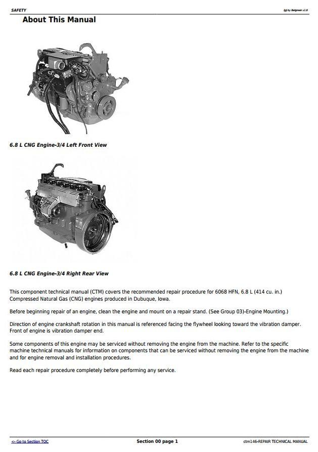
About This Manual
Safety
Handle Fluids Safely-Avoid Fires
Handle Natural Gas Safely
Prevent Battery Explosions
Prepare for Emergencies
Prevent Acid Burns
Avoid High-Pressure Fluids
Wear Protective Clothing
Service Machines Safely
Work in Ventilated Area
Work in Clean Area
Remove Paint Before Welding or Heating
Avoid Heating Near Pressurized Fluid Lines
Illuminate Work Area Safely
Use Proper Lifting Equipment
Practice Safe Maintenance
Use Proper Tools
Dispose of Waste Properly
Handle Compressed Natural Gas (CNG) Safely
Service Compressed Natural Gas (CNG) Systems Safely
Protect Against High Pressure
Protect Against Extremely Cold CNG Leakage
Live With Safety
General Information
Unified Inch Bolt and Cap Screw Torque Values
Metric Bolt and Cap Screw Torque Values
Engine Model Designation
Engine Serial Number Plate Information
Fuels, Lubricants, and Coolant
Natural Gas Recommendations
Natural Gas Engine Oil
Engine Break-In Oil
Alternative and Synthetic Lubricants
Mixing of Lubricants
OILSCANOILSCAN is a trademark of Deere & Company. and CoolScanCoolScan is a trademark of Deere & Company.
Grease
Recommended Engine Coolant
Engine Coolant Specifications
Testing Diesel Engine Coolant
Replenishing Supplemental Coolant Additives (SCA’s) Between Coolant Changes
Operating in Warm Temperature Climates
Flush and Service Cooling System
Disposing of Coolant
Engine Mounting
Engine Repair Stand
Safety Precautions
Install Adapters on Engine Repair Stand
Engine Lifting Procedure
Clean Engine
Disconnect Turbocharger Oil Inlet Line
Mount Engine on Repair Stand
Engine Mounted on Repair Stand
Engine Rebuild Guide
Engine Disassembly Sequence
Sealant Application Guidelines
Engine Assembly Sequence
Cylinder Head and Valves
Special or Essential Tools
Service Equipment and Tools
Other Material
Cylinder Head and Valves Specifications
Check and Adjust Valve Clearance
Measure Valve Lift
Remove Cylinder Head
Disassemble and Inspect Rocker Arm Shaft Assembly
Assemble Rocker Arm Assembly
Inspect, Measure, and Assemble Camshaft Followers
Measure Valve Recess in Cylinder Head
Preliminary Cylinder Head and Valve Checks
Remove Valve Assembly
Inspect and Measure Valve Springs
Inspect Valve Rotators
Clean Valves
Inspect and Measure Valves
Grind Valves
Inspect and Clean Cylinder Head
Check Cylinder Head Flatness
Measure Cylinder Head Thickness
Clean Valve Guides
Measure Valve Guides
Knurl Valve Guides
Clean and Inspect Valve Seats
Grind Valve Seats
Remove Valve Seat Inserts
Measure Valve Seat Bore in Cylinder Head
Install Valve Seat Inserts
Install Valves
Inspect and Clean Exhaust Manifold
Clean and Inspect Top Deck of Cylinder Block
Measure Cylinder Liner Standout (Height Above Block)
Install Cylinder Head and Cap Screws
Torque-Turn Method for Proper Torque
Install Rocker Arm Assembly
Inspect and Clean Ventilator Outlet Hose
Install Rocker Arm Cover
Complete Final Assembly
Perform Engine Break-In
Cylinder Block, Liners, Pistons, and Rods
Special or Essential Tools
Service Equipment and Tools
Other Material
Cylinder Block, Liners, Pistons, and Rods Specifications
Connecting Rods-General Information
Remove Pistons and Connecting Rods
Remove Cylinder Liners
Complete Disassembly of Cylinder Block (If Required)
Preliminary Liner, Piston and Rod Checks
Disassemble Piston and Rod Assembly
Clean Pistons
Visually Inspect Pistons
Clean Cylinder Liners
Visually Inspect Cylinder Liners
Check Piston Ring Groove Wear
Measure Piston Pin Bore
Measure Piston Skirt
Determine Piston-to-Liner Clearance
Deglaze Cylinder Liners
Replace Piston and Liner Sets
Inspect and Measure Connecting Rod Bearings
Inspect Rod and Cap
Inspect Piston Pins and Bushings
Remove Piston Pin Bushing
Clean and Inspect Connecting Rod Pin Bore
Install Piston Pin Bushing in Connecting Rod
Measure Rod Center-to-Center Bores
Inspect and Clean Cylinder Block
Clean Cylinder Liner O-Ring Bore
Measure Cylinder Block Main Bearing Bore
Measure Camshaft Follower Machined Bore in Block
Measure Camshaft Bushing Bores in Block
Measure Liner Flange Counterbore Depth in Block
Measure Liner Flange Thickness
Measure Cylinder Block Top Deck Flatness
Remove, Inspect, and Install Piston Cooling Orifices
Measure Cylinder Liner Standout (Height Above Block)
Install Packing on Cylinder Liner and O-Rings in Block
Install Cylinder Liner in Block
Assemble Connecting Rods onto Piston
Install Piston Rings
Connecting Rods-General Information
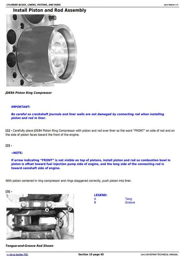
Install Piston and Rod Assembly
Torque-Turn Connecting Rod Cap Screws
Check Engine Rotation for Excessive Tightness
Measure Piston Protrusion
Complete Final Assembly
Crankshaft, Main Bearings, and Flywheel
Special or Essential Tools
Service Equipment and Tools
Other Material
Crankshaft, Main Bearings, and Flywheel Specifications
Crankshaft Grinding Specifications
Crankshaft and Main Bearing Failure Analysis
Inspect Vibration Damper
Remove Pulley or Vibration Damper and Pulley
Install Pulley or Vibration Damper Pulley
Checking Vibration Damper or Pulley
Replace Front Crankshaft Oil Seal and Wear Sleeve (Without Removing Timing Gear Cover)
Check Crankshaft End Play
Inspect Flywheel
Remove Flywheel
Replace Flywheel Ring Gear
Install Flywheel
Crankshaft Rear Oil Seal and Wear Sleeve Handling Precautions
Remove Unitized (Non-Separable) Crankshaft Rear Oil Seal and Wear Sleeve
Install Crankshaft Rear Oil Seal and Wear Sleeve
Remove Flywheel Housing
Remove Crankshaft Main Bearings
Check Main Bearing Oil Clearance
Remove and Install Crankshaft Gear (Crankshaft Installed In Engine)
Remove Crankshaft
Inspect Crankshaft
Measure Assembled Main Bearing ID and OD of Crankshaft Main Journal and Rod Journal
Measure Main Thrust Journal Width and Thrust Bearing Width
Crankshaft Grinding Guidelines
Measure Assembled ID of Main Bearing Caps
Remove, Inspect, and Install Piston Cooling Orifices
Install Main and Thrust Bearing Inserts in Block
Install Crankshaft
Install Flywheel Housing
Complete Final Assembly
Camshaft and Timing Gear Train
Special or Essential Tools
Service Equipment and Tools
Other Material
Camshaft and Timing Gear Train Specifications
Measure Valve Lift
Remove Timing Gear Cover
Remove and Install Camshaft Bushing With Front Plate Installed
Measure Camshaft End Play
Measure Idler Gear End Play
Measure Timing Gear Backlash
Remove Camshaft
Visually Inspect Camshaft
Measure Camshaft Thrust Plate Clearance
Inspect and Measure Camshaft Bushing ID and Journal OD
Measure Camshaft Lobe Height
Remove and Install Camshaft Gear
Inspect Camshaft Followers
Remove Cylinder Block Front Plate
Measure Idler Gear Bushing and Shaft
Remove and Install Idler Gear Bushing
Remove Lower and Upper Idler Shafts
Clean and Inspect Front Plate
Install Idler Shaft Spring Pins
Install Upper Idler Shaft in Front Plate
Install Lower Idler Shaft in Front Plate
Install Engine Front Plate
Install and Time Camshaft
Clean and Inspect Timing Gear Cover
Install Timing Gear Cover
Install Crankshaft Front Wear Sleeve and Oil Seal
Complete Final Assembly
Lubrication System
Special or Essential Tools
Service Equipment and Tools
Other Material
Lubrication System Specifications
Diagnosing Lubrication System Malfunctions
Remove, Inspect, and Install Oil Filter Base
Remove, Inspect, and Install Oil Cooler
Remove, Inspect, and Install Oil Bypass Valve
Remove and Install Oil Pressure Regulating Valve and Seat
Remove and Install Oil Fill Tube
Remove and Install Dipstick Tube With Oil Pan Installed
Replace Oil Pump Pick-Up Tube Assembly
Engine Oil Pump Assembly
Remove Engine Oil Pump
Inspect and Measure Clearances
Complete Oil Pump Disassembly
Assemble Engine Oil Pump
Install Engine Oil Pump
Install Oil Pan
Cooling System
Special or Essential Tools
Service Equipment and Tools
Other Material
Cooling System Specifications
Diagnosing Cooling System Malfunctions
Remove Water Manifold/Thermostat Cover and Thermostat
Test Thermostat
Install Water Manifold/Thermostat Cover and Thermostat
Remove Water Pump
Water Pump Assembly
Disassemble Water Pump
Inspect, Clean, and Measure Water Pump Parts
Assemble Water Pump
Install Water Pump
Remove and Install Automatic (Spring) Belt Tensioner
Checking Belt Tensioner Spring Tension and Belt Wear
Remove and Inspect Idler Pulley Assembly
Replace Bearing in Idler Pulley Assembly
Install Idler Pulley Assembly
Remove and Install Coolant Heater
Air Intake and Exhaust System
Other Material
Air Intake and Exhaust System Specifications
Extending Turbocharger Life
Remove Turbocharger
Turbocharger Failure Analysis
Turbocharger Seven-Step Inspection
Perform Axial Bearing End Play Test
Repair Turbocharger
Clean and Inspect Turbine and Compressor Housings
Adjust Turbocharger Wastegate Actuator
Prelube Turbocharger
Install Turbocharger
Cleaning PCV Orifice
Remove, Inspect, and Install Exhaust Manifold
Remove, Inspect, and Install Intake Manifold
Fuel Supply System
Specifications
Fuel Pressure Leak-Off Procedure
Leak Check Procedure
Remove and Install Natural Gas Regulator
Repair Natural Gas Regulator
Remove and Install Fuel Metering Valve
Repair Fuel Metering Valve
Remove and Install Fuel Mixer
Starting and Charging System
Special or Essential Tools
Specifications
Remove and Install Starter
Bench Test Starting Motor
Make Solenoid Return Test
Make No Load Test
Diagnose No Load Test
Remove and Install Alternator
Charging System Failure
Alternator Troubleshooting
Alternator Output Test
Diode Trio Test
Full Field Test
Electronic Engine Controls
Special or Essential Tools
Service Equipment and Tools
Other Material
Specifications
Remove and Install Spark Plugs
Removal of Seized Spark Plugs (Tool JDG1193 Not Available or Spark Plug Ceramic Stem Has Broken Off)
Remove and Install Ignition Coils
Remove and Install Ignition Control Unit (ICU)
Remove and Install Cam Sensor
Remove and Install Crank Sensor
Remove and Install Engine Coolant Temperature (ECT) Sensor
Remove and Install Foot Pedal Position Sensor
Remove and Install Manifold Absolute Pressure (MAP) Sensor
Remove and Install Manifold Air Temperature (MAT) Sensor
Remove and Install Natural Gas Tank Temperature (NGTT) Sensor
Remove and Install Preturbine Pressure (PTP) Sensor
Remove and Install Exhaust Back Pressure (EBP) Sensor
Remove and Install Electronic Throttle and Throttle Position Sensor
Remove and Install Universal Exhaust Gas Oxygen (UEGO) Sensor
Remove and Install Oil Pressure Switch
Remove and Install Turbocharger Wastegate Control Valve
Natural Gas Engine Wiring Harness
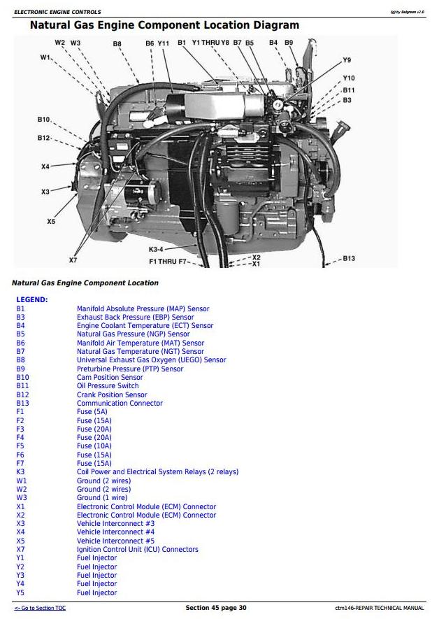
Natural Gas Engine Component Location Diagram
Connectors
Using High-Pressure Washer
Replace WEATHER PACK WEATHER PACK is a trademark of Packard Electric. Connector
Install WEATHER PACK WEATHER PACK is a trademark of Packard Electric. Contact
Remove Connector Body from Blade Terminals
Replace (Pull Type) METRI-PACK METRI-PACK is a trademark of Packard Electric. Connectors
Replace (Push Type) METRI-PACK METRI-PACK is a trademark of Packard Electric. Connectors
Use Electrical Insulating Compound
Replace DEUTSCH DEUTSCH is a trademark of the Deutsch Co. Connectors
Install DEUTSCH DEUTSCH is a trademark of the Deutsch Co. Contact
Miscellaneous Accessories
Other Material
Miscellaneous Accessories Specifications
Remove Air Compressor
Inspecting Air Compressor
Remove Idler Housing
Install Idler Housing
Install Air Compressor
Dealer Fabricated Tools
Dealer Fabricated Tools
DFRG3 Cylinder Liner Holding Fixture

Format: PDF
Language: English
Type of Document: Component Technical Manual
Type of Machine: PowerTech
Number of Pages: 485 pages
Part Number: CTM146
Model: John Deere 6.8L 6068 Repair Component Technical Manual
John Deere 6068CNG
Content:
Foreword
About This Manual
Safety
Handle Fluids Safely-Avoid Fires
Handle Natural Gas Safely
Prevent Battery Explosions
Prepare for Emergencies
Prevent Acid Burns
Avoid High-Pressure Fluids
Wear Protective Clothing
Service Machines Safely
Work in Ventilated Area
Work in Clean Area
Remove Paint Before Welding or Heating
Avoid Heating Near Pressurized Fluid Lines
Illuminate Work Area Safely
Use Proper Lifting Equipment
Practice Safe Maintenance
Use Proper Tools
Dispose of Waste Properly
Handle Compressed Natural Gas (CNG) Safely
Service Compressed Natural Gas (CNG) Systems Safely
Protect Against High Pressure
Protect Against Extremely Cold CNG Leakage
Live With Safety
General Information
Unified Inch Bolt and Cap Screw Torque Values
Metric Bolt and Cap Screw Torque Values
Engine Model Designation
Engine Serial Number Plate Information
Fuels, Lubricants, and Coolant
Natural Gas Recommendations
Natural Gas Engine Oil
Engine Break-In Oil
Alternative and Synthetic Lubricants
Mixing of Lubricants
OILSCANOILSCAN is a trademark of Deere & Company. and CoolScanCoolScan is a trademark of Deere & Company.
Grease
Recommended Engine Coolant
Engine Coolant Specifications
Testing Diesel Engine Coolant
Replenishing Supplemental Coolant Additives (SCA’s) Between Coolant Changes
Operating in Warm Temperature Climates
Flush and Service Cooling System
Disposing of Coolant
Engine Mounting
Engine Repair Stand
Safety Precautions
Install Adapters on Engine Repair Stand
Engine Lifting Procedure
Clean Engine
Disconnect Turbocharger Oil Inlet Line
Mount Engine on Repair Stand
Engine Mounted on Repair Stand
Engine Rebuild Guide
Engine Disassembly Sequence
Sealant Application Guidelines
Engine Assembly Sequence
Cylinder Head and Valves
Special or Essential Tools
Service Equipment and Tools
Other Material
Cylinder Head and Valves Specifications
Check and Adjust Valve Clearance
Measure Valve Lift
Remove Cylinder Head
Disassemble and Inspect Rocker Arm Shaft Assembly
Assemble Rocker Arm Assembly
Inspect, Measure, and Assemble Camshaft Followers
Measure Valve Recess in Cylinder Head
Preliminary Cylinder Head and Valve Checks
Remove Valve Assembly
Inspect and Measure Valve Springs
Inspect Valve Rotators
Clean Valves
Inspect and Measure Valves
Grind Valves
Inspect and Clean Cylinder Head
Check Cylinder Head Flatness
Measure Cylinder Head Thickness
Clean Valve Guides
Measure Valve Guides
Knurl Valve Guides
Clean and Inspect Valve Seats
Grind Valve Seats
Remove Valve Seat Inserts
Measure Valve Seat Bore in Cylinder Head
Install Valve Seat Inserts
Install Valves
Inspect and Clean Exhaust Manifold
Clean and Inspect Top Deck of Cylinder Block
Measure Cylinder Liner Standout (Height Above Block)
Install Cylinder Head and Cap Screws
Torque-Turn Method for Proper Torque
Install Rocker Arm Assembly
Inspect and Clean Ventilator Outlet Hose
Install Rocker Arm Cover
Complete Final Assembly
Perform Engine Break-In
Cylinder Block, Liners, Pistons, and Rods
Special or Essential Tools
Service Equipment and Tools
Other Material
Cylinder Block, Liners, Pistons, and Rods Specifications
Connecting Rods-General Information
Remove Pistons and Connecting Rods
Remove Cylinder Liners
Complete Disassembly of Cylinder Block (If Required)
Preliminary Liner, Piston and Rod Checks
Disassemble Piston and Rod Assembly
Clean Pistons
Visually Inspect Pistons
Clean Cylinder Liners
Visually Inspect Cylinder Liners
Check Piston Ring Groove Wear
Measure Piston Pin Bore
Measure Piston Skirt
Determine Piston-to-Liner Clearance
Deglaze Cylinder Liners
Replace Piston and Liner Sets
Inspect and Measure Connecting Rod Bearings
Inspect Rod and Cap
Inspect Piston Pins and Bushings
Remove Piston Pin Bushing
Clean and Inspect Connecting Rod Pin Bore
Install Piston Pin Bushing in Connecting Rod
Measure Rod Center-to-Center Bores
Inspect and Clean Cylinder Block
Clean Cylinder Liner O-Ring Bore
Measure Cylinder Block Main Bearing Bore
Measure Camshaft Follower Machined Bore in Block
Measure Camshaft Bushing Bores in Block
Measure Liner Flange Counterbore Depth in Block
Measure Liner Flange Thickness
Measure Cylinder Block Top Deck Flatness
Remove, Inspect, and Install Piston Cooling Orifices
Measure Cylinder Liner Standout (Height Above Block)
Install Packing on Cylinder Liner and O-Rings in Block
Install Cylinder Liner in Block
Assemble Connecting Rods onto Piston
Install Piston Rings
Connecting Rods-General Information
Install Piston and Rod Assembly
Torque-Turn Connecting Rod Cap Screws
Check Engine Rotation for Excessive Tightness
Measure Piston Protrusion
Complete Final Assembly
Crankshaft, Main Bearings, and Flywheel
Special or Essential Tools
Service Equipment and Tools
Other Material
Crankshaft, Main Bearings, and Flywheel Specifications
Crankshaft Grinding Specifications
Crankshaft and Main Bearing Failure Analysis
Inspect Vibration Damper
Remove Pulley or Vibration Damper and Pulley
Install Pulley or Vibration Damper Pulley
Checking Vibration Damper or Pulley
Replace Front Crankshaft Oil Seal and Wear Sleeve (Without Removing Timing Gear Cover)
Check Crankshaft End Play
Inspect Flywheel
Remove Flywheel
Replace Flywheel Ring Gear
Install Flywheel
Crankshaft Rear Oil Seal and Wear Sleeve Handling Precautions
Remove Unitized (Non-Separable) Crankshaft Rear Oil Seal and Wear Sleeve
Install Crankshaft Rear Oil Seal and Wear Sleeve
Remove Flywheel Housing
Remove Crankshaft Main Bearings
Check Main Bearing Oil Clearance
Remove and Install Crankshaft Gear (Crankshaft Installed In Engine)
Remove Crankshaft
Inspect Crankshaft
Measure Assembled Main Bearing ID and OD of Crankshaft Main Journal and Rod Journal
Measure Main Thrust Journal Width and Thrust Bearing Width
Crankshaft Grinding Guidelines
Measure Assembled ID of Main Bearing Caps
Remove, Inspect, and Install Piston Cooling Orifices
Install Main and Thrust Bearing Inserts in Block
Install Crankshaft
Install Flywheel Housing
Complete Final Assembly
Camshaft and Timing Gear Train
Special or Essential Tools
Service Equipment and Tools
Other Material
Camshaft and Timing Gear Train Specifications
Measure Valve Lift
Remove Timing Gear Cover
Remove and Install Camshaft Bushing With Front Plate Installed
Measure Camshaft End Play
Measure Idler Gear End Play
Measure Timing Gear Backlash
Remove Camshaft
Visually Inspect Camshaft
Measure Camshaft Thrust Plate Clearance
Inspect and Measure Camshaft Bushing ID and Journal OD
Measure Camshaft Lobe Height
Remove and Install Camshaft Gear
Inspect Camshaft Followers
Remove Cylinder Block Front Plate
Measure Idler Gear Bushing and Shaft
Remove and Install Idler Gear Bushing
Remove Lower and Upper Idler Shafts
Clean and Inspect Front Plate
Install Idler Shaft Spring Pins
Install Upper Idler Shaft in Front Plate
Install Lower Idler Shaft in Front Plate
Install Engine Front Plate
Install and Time Camshaft
Clean and Inspect Timing Gear Cover
Install Timing Gear Cover
Install Crankshaft Front Wear Sleeve and Oil Seal
Complete Final Assembly
Lubrication System
Special or Essential Tools
Service Equipment and Tools
Other Material
Lubrication System Specifications
Diagnosing Lubrication System Malfunctions
Remove, Inspect, and Install Oil Filter Base
Remove, Inspect, and Install Oil Cooler
Remove, Inspect, and Install Oil Bypass Valve
Remove and Install Oil Pressure Regulating Valve and Seat
Remove and Install Oil Fill Tube
Remove and Install Dipstick Tube With Oil Pan Installed
Replace Oil Pump Pick-Up Tube Assembly
Engine Oil Pump Assembly
Remove Engine Oil Pump
Inspect and Measure Clearances
Complete Oil Pump Disassembly
Assemble Engine Oil Pump
Install Engine Oil Pump
Install Oil Pan
Cooling System
Special or Essential Tools
Service Equipment and Tools
Other Material
Cooling System Specifications
Diagnosing Cooling System Malfunctions
Remove Water Manifold/Thermostat Cover and Thermostat
Test Thermostat
Install Water Manifold/Thermostat Cover and Thermostat
Remove Water Pump
Water Pump Assembly
Disassemble Water Pump
Inspect, Clean, and Measure Water Pump Parts
Assemble Water Pump
Install Water Pump
Remove and Install Automatic (Spring) Belt Tensioner
Checking Belt Tensioner Spring Tension and Belt Wear
Remove and Inspect Idler Pulley Assembly
Replace Bearing in Idler Pulley Assembly
Install Idler Pulley Assembly
Remove and Install Coolant Heater
Air Intake and Exhaust System
Other Material
Air Intake and Exhaust System Specifications
Extending Turbocharger Life
Remove Turbocharger
Turbocharger Failure Analysis
Turbocharger Seven-Step Inspection
Perform Axial Bearing End Play Test
Repair Turbocharger
Clean and Inspect Turbine and Compressor Housings
Adjust Turbocharger Wastegate Actuator
Prelube Turbocharger
Install Turbocharger
Cleaning PCV Orifice
Remove, Inspect, and Install Exhaust Manifold
Remove, Inspect, and Install Intake Manifold
Fuel Supply System
Specifications
Fuel Pressure Leak-Off Procedure
Leak Check Procedure
Remove and Install Natural Gas Regulator
Repair Natural Gas Regulator
Remove and Install Fuel Metering Valve
Repair Fuel Metering Valve
Remove and Install Fuel Mixer
Starting and Charging System
Special or Essential Tools
Specifications
Remove and Install Starter
Bench Test Starting Motor
Make Solenoid Return Test
Make No Load Test
Diagnose No Load Test
Remove and Install Alternator
Charging System Failure
Alternator Troubleshooting
Alternator Output Test
Diode Trio Test
Full Field Test
Electronic Engine Controls
Special or Essential Tools
Service Equipment and Tools
Other Material
Specifications
Remove and Install Spark Plugs
Removal of Seized Spark Plugs (Tool JDG1193 Not Available or Spark Plug Ceramic Stem Has Broken Off)
Remove and Install Ignition Coils
Remove and Install Ignition Control Unit (ICU)
Remove and Install Cam Sensor
Remove and Install Crank Sensor
Remove and Install Engine Coolant Temperature (ECT) Sensor
Remove and Install Foot Pedal Position Sensor
Remove and Install Manifold Absolute Pressure (MAP) Sensor
Remove and Install Manifold Air Temperature (MAT) Sensor
Remove and Install Natural Gas Tank Temperature (NGTT) Sensor
Remove and Install Preturbine Pressure (PTP) Sensor
Remove and Install Exhaust Back Pressure (EBP) Sensor
Remove and Install Electronic Throttle and Throttle Position Sensor
Remove and Install Universal Exhaust Gas Oxygen (UEGO) Sensor
Remove and Install Oil Pressure Switch
Remove and Install Turbocharger Wastegate Control Valve
Natural Gas Engine Wiring Harness
Natural Gas Engine Component Location Diagram
Connectors
Using High-Pressure Washer
Replace WEATHER PACK WEATHER PACK is a trademark of Packard Electric. Connector
Install WEATHER PACK WEATHER PACK is a trademark of Packard Electric. Contact
Remove Connector Body from Blade Terminals
Replace (Pull Type) METRI-PACK METRI-PACK is a trademark of Packard Electric. Connectors
Replace (Push Type) METRI-PACK METRI-PACK is a trademark of Packard Electric. Connectors
Use Electrical Insulating Compound
Replace DEUTSCH DEUTSCH is a trademark of the Deutsch Co. Connectors
Install DEUTSCH DEUTSCH is a trademark of the Deutsch Co. Contact
Miscellaneous Accessories
Other Material
Miscellaneous Accessories Specifications
Remove Air Compressor
Inspecting Air Compressor
Remove Idler Housing
Install Idler Housing
Install Air Compressor
Dealer Fabricated Tools
Dealer Fabricated Tools
DFRG3 Cylinder Liner Holding Fixture
More the random threads same category:
- JOHN DEERE JD-410 Technical Manual
- Funk Power DF Series 150 & 250 Transmission Service Manual
- John Deere Service ADVISOR 4.0 CF+JDIN+History Data (11.2013)
- John Deere Parts Manager Pro 6.5.5 (CF) Construction & Foresty [03.2016]
- John Deere Service Advisor 4.1.011 + 4 dvd data RU (01.2013)
- John Deere 750C,850C Crawler Dozer Technical Manual
- John Deere Service Advisor 4.01.11
- John Deere 750J,850J Crawler Dozer Parts Catalog
- John Deere 6020 Series Repair Manuals (6020 to 6920S)
- John Deere Service Advisor 4.1.007 Torrent 28.11.2013
- Jonh Dree 690E LC Excavator Techical Manual
- John Deere 700J Crawler Dozer Parts Catalog
- John Deere 850J Crawler Dozer Tier 3 Parts Catalog
- John Deere LTR155, LTR166 and LTR180 Lawn Tractors Technical manual
- JOHN DEERE CODE DTC LIST