

Yanmar Engine 3YM30 3YM20 2YM15 Service Manual M9961-03E101
- Download this document, you need 1050 Gallons
Yanmar Engine 3YM30 3YM20 2YM15 Service Manual M9961-03E101
Size: 15.71 MB
Format: PDF
Language: English
Brand: Yanmar
Type of Machine: Engine
Type of Manual: Service Manual, Wiring Diagram
Model: Yanmar 3YM30 3YM20 2YM15 Engine
Part Number: M9961-03E101
Number of Pages: 231 Pages
Contents:
1. General
Back cover


Size: 15.71 MB
Format: PDF
Language: English
Brand: Yanmar
Type of Machine: Engine
Type of Manual: Service Manual, Wiring Diagram
Model: Yanmar 3YM30 3YM20 2YM15 Engine
Part Number: M9961-03E101
Number of Pages: 231 Pages
Contents:
1. General
1.1 Exterior views
1.2 Specifications
1.3 Fuel oil, lubricating oil and cooling water
1.3.1 Fuel oil
1.3.2 Lubricating oil
1.3.3 Cooling water
1.4 Engine outline
1.5 Piping diagrams
1.6 Exhaust gas emission regulation
1.6.1 Engine identification (EPA/ARB)
1.6.2 Exhaust gas emission standard (EPA/ARB)
1.6.3 Guarantee conditions for emission standard (EPA/ARB)
2. Inspection and adjustment2.1 Periodic maintenance schedule
2.2 Periodic inspection and maintenance procedure
2.2.1 Check before starting
2.2.2 inspection after initial 50 hours or one month operation
2.2.3 Inspection every 50 hours or monthly
2.2.4 Inspection every 100 hours six months
2.2.5 Inspection every 150 hours or one year
2.2.6 Inspection every 250 hours or one year
2.2.7 Inspection every 1,000 hours or four years
2.3 Adjusting the no-load maximum or minimum speed
2.4 Sensor Inspection
2.4.1 Oil pressure switch
2.4.2 Thermo switch
2.5 Thermostat inspection
2.6 Adjusting operation
2.6.1 Preliminary precautions
2.6.2 Adjusting operation procedure
2.6.3 Check points and precautions during running
2.7 Long storage
3. Troubleshooting3.1 Preparation before troubleshooting
3.2 Quick reference chart for troubleshooting
3.3 Troubleshooting (Concerning engine and fuel injection equipment)
3.4 Troubleshooting by measuring compression pressure
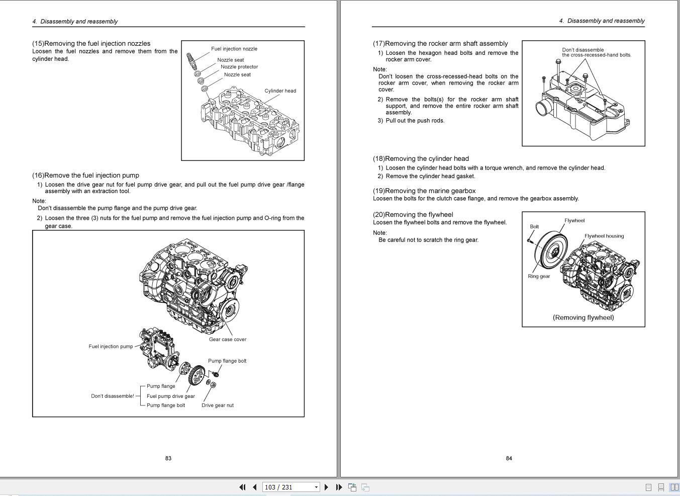
4. Disassembly and reassembly4.1 Disassembly and reassembly precautions
4.2 Disassembly and reassembly tools
4.2.1 General hand tools
4.2.2 Special hand tools
4.2.3 Measuring instruments
4.2.4 Other material
4.3 Disassembly and reassembly
4.3.1 Disassembly
4.3.2 Reassembly
5. Inspection and servicing of basic engine parts5.1 Cylinder block
5.1.1 Inspection of parts
5.1.2 Cleaning of oil holes
5.1.3 Color check procedure
5.1.4 Replacement of cap plugs
5.1.5 Cylinder bore measurement
5.2 Cylinder head
5.2.1 Inspecting the cylinder head
5.2.2 Valve seat correction procedure
5.2.3 Intake/exhaust valves, valve guides
5.2.4 Valve springs
5.2.5 Assembling the cylinder head
5.2.6 Measuring top clearance
5.2.7 Intake and exhaust rocker arms
5.2.8 Adjustment of valve clearance
5.3 Piston and piston pins
5.3.1 Piston
5.3.2 Piston pin
5.3.3 Piston rings
5.4 Connecting rod
5.4.1 Inspecting the connection rod
5.4.2 Crank pin metal
5.4.3 Piston pin bushing
5.4.4 Assembling piston and connecting rod
5.5 Crankshaft and main bearing
5.5.1 Crankshaft
5.5.2 Main bearing
5.6 Camshaft and tappets
5.6.1 Camshaft
5.6.2 Tappets
5.7 Timing gear
5.7.1 Inspecting the gears
5.7.2 Gear timing marks
5.8 Flywheel and housing
5.8.1 Position of top dead center and fuel injection timing
5.8.2 Damper disc
6. Fuel injection equipment6.1 Fuel Injection pump/governor
6.1.1 Fuel system diagram
6.1.2 Fuel injection pump service data and adjustment
6.1.3 Fuel injection pump structure
6.1.4 Removing a fuel injection pump
6.1.5 Installing a fuel injection pump
6.1.6 Adjusting fuel injection timing
6.1.7 Troubleshooting of fuel injection pump
6.1.8 Major faults and troubleshooting
6.2 Fuel feed pump
6.2.1 Construction of fuel feed pump
6.2.2 Fuel feed pump specifications
6.2.3 Disassembly and reassembly of fuel feed pump
6.2.4 Fuel feed pump inspection
6.3 Fuel filter
6.3.1 Fuel filter specifications
6.3.2 Fuel filter inspection
6.4 Fuel tank
7. Intake and exhaust system7.1 Intake system
7.1.1 Breather system (A reductor to intake air system of blowby gas)
7.1.2 Diaphragm assy inspection
7.2 Exhaust system
7.2.1 Construction
7.2.2 Mixing elbow inspection
8. Lubrication system8.1 Lubrication system
8.2 Lube oil pump
8.2.1 Lube oil pump construction
8.2.2 Specifications of lube oil pump
8.2.3 Lube oil pump disassembly and reassembly
8.2.4 Lube oil pump inspection
8.2.5 Pressure control valve construction
8.3 Lube oil filter
8.3.1 Lube oil filter construction
8.3.2 Lube oil filter replacement
8.4 Rotary waste oil pump (Optional)
9. Cooling water system9.1 Cooling water system
9.2 Seawater pump
9.2.1 Specifications of seawater pump
9.2.2 Seawater pump disassembly
9.2.3 Seawater pump Inspection
9.2.4 Seawater pump reassembly
9.3 Fresh water pump
9.3.1 Fresh water pump construction
9.3.2 Specifications of fresh water pump
9.3.3 Fresh water pump disassembly
9.3.4 WFresh water pump inspection
9.4 Heat exchanger
9.4.1 Heat exchanger construction
9.4.2 Disassembly and reassembly of the heat exchanger
9.4.3 Heat exchanger inspection
9.5 Pressure cap and coolant recovery tank
9.5.1 Pressure cap construction
9.5.2 Pressure cap pressure control
9.5.3 Pressure cap inspection
9.5.4 Replacing filler neck
9.5.5 Function of the coolant recovery tank
9.5.6 Specifications of coolant recovery tank
9.5.7 Mounting the coolant recovery tank
9.5.8 Precautions on usage of the coolant recovery tank
9.6 Thermostat
9.6.1 Functioning of thermostat
9.6.2 Thermostat construction
9.6.3 Characteristics of thermostat
9.6.4 Thermostat inspection
9.6.5 Testing the thermostat
9.7 Bilge pump and bilge strainer (Optional)
9.7.1 Introduction
9.7.2 Description
9.7.3 Cautions
9.7.4 Assembly procedure
9.7.5 Cautions for assembling
9.7.6 Troubleshooting
10. Reduction and reversing gear10.1 Specifications
11. Remote control (Optional)11.1 Remote control system
11.1.1 Construction of remote control system
11.1.2 Remote control device components
11.2 Remote control installation
11.3 Remote control inspection
11.4 Remote control adjustment
12. Electrical system12.1 Electrical system
12.1.1 Wiring diagram
12.2 Battery
12.3 Starting motor
12.3.1 Specifications
12.3.2 Characteristics
12.3.3 Structure
12.3.4 Wiring diameter of a starting motor
12.4 Alternator standard, 12V/60A
12.4.1 Specifications
12.4.2 Structure
12.4.3 Wiring diagram
12.4.4 Standard output characteristics
12.4.5 Inspection
12.5 Alternator 12V/80A (Optional)
12.5.1 Specifications
12.5.2 Structure
12.5.3 Wiring diagram
12.5.4 Standard output characteristics
12.6 Instrument panel
12.6.1 B-type instrument panel (Optional)
12.7 Warning devices
12.7.1 Oil pressure alarm
12.7.2 Cooling water temperature alarm
12.8 Glow plug
12.9 Electric engine stopping device
13. Service standards13.1 Engine tuning
13.2 Engine body
13.2.1 Cylinder head
13.2.2 Camshaft and gear train
13.2.3 Cylinder block
13.3 Lubricating oil system (Trochoid pump)
14. Tightening torque for bolts and nuts14.1 Main bolt and nut
14.2 Standard bolts and nuts (without lube oil)
ColophonBack cover
More the random threads same category:
- Yanmar Mini-Excavators B25V Service Manual
- YANMAR Crawler Backhoe model YB121U, YB151U ,YB121U-2, YB151U-2 Parts Catalog
- YANMAR Crawler Backhoe model YB451(-2) YB501(-2) Parts Catalog
- YANMAR Crawler Backhoe model YB201 (U) Parts Catalog
- YANMAR Crawler Backhoe model YB301(-1,-2) YB351(-1,-2) Parts Catalog
- Yanmar D27, D36 Marine Diesel Engine Service Manual
- YANMAR Wheel Backhoe model YB401W and YB401W-2 Parts Catalog
- YANMAR Crawler Backhoe model Vio70 for Europe Parts Catalog
- YANMAR AMMANN CRAWLER BACKHOE B12/B17 PARTS MANUAL
- YANMAR Crawler Backhoe model Vio 20 Parts Catalog
- YANMAR Crawler Backhoe model YB101 and B10 Parts Catalog
- Yanmar Engine 3TNA72L-UTB(YB10-2)Parts Catalog
- YANMAR Engine 2TR15/16/17/19/20/20C Parts Catalog
- YANMAR Tractor YM14 Parts Manual
- Yanmar Excavator ViO45-5 ViO55-5 Service Manual