

- Gallons
- 230,310
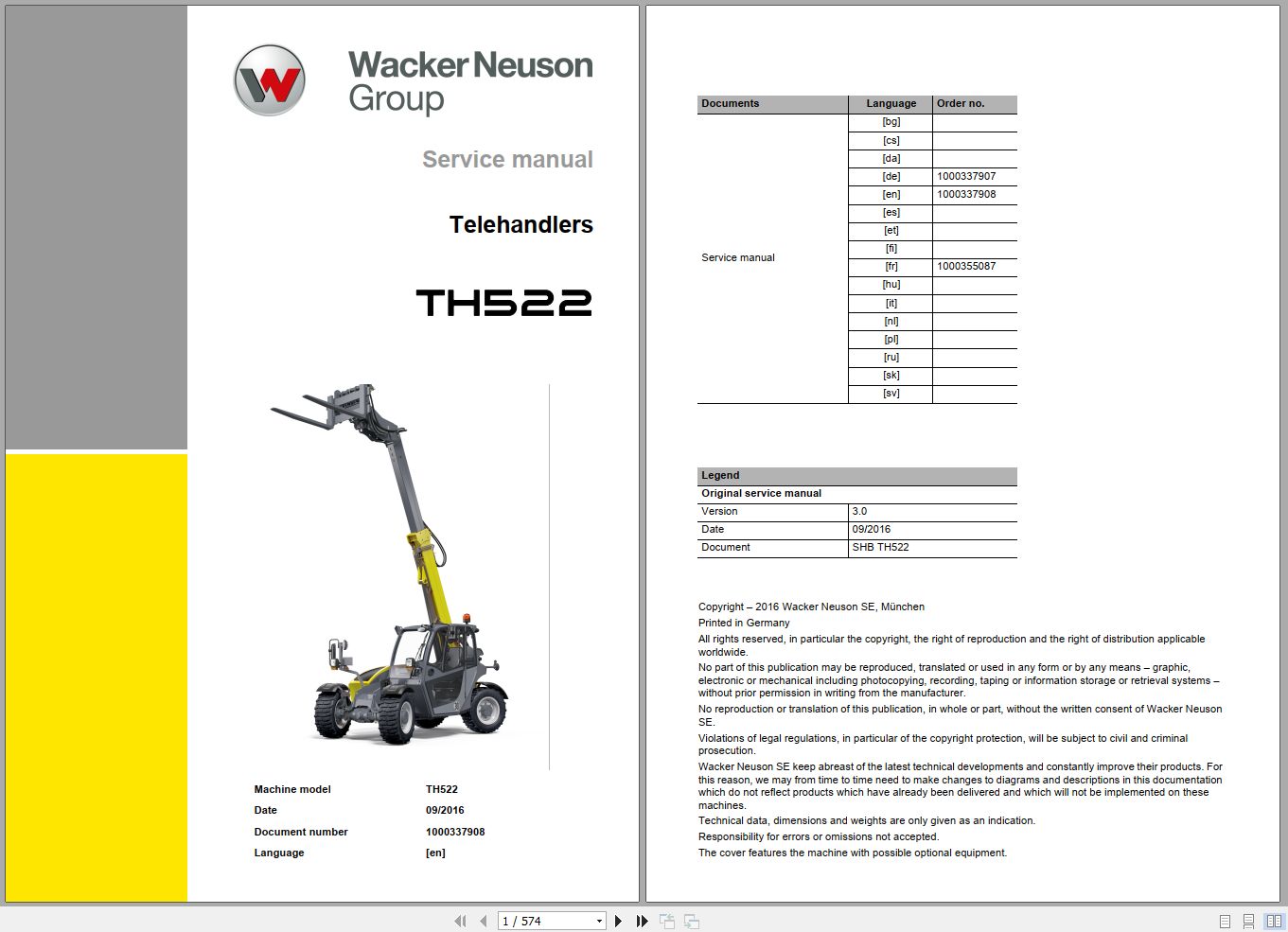
Wacker Neuson Telehandlers TH522 Service Manual and Diagram 1000337908
- Download this document, you need 1050 Gallons
Wacker Neuson Telehandlers TH522 Service Manual and Diagram 1000337908
Size: 81.80 MB
Format: PDF
Language: English
Brand: Wacker Neuson
Type of Machine: Telehandlers
Type of Manual: Service Manual, Electrical and Hydraulic Diagram
Model: Wacker Neuson TH522 Telehandlers
Part Number: 1000337908
Publication Date: 2016
Number of Pages: 574 Pages
Contents:
E Introduction
E.1 About this Service Manual
E.2 Tightening torques
E.3 Safety instructions
B Operation
B.1 Overview of control elements
B.2 Indicator lights and warning lights (overview)
B.3 Steering system
B.4 Accelerator actuation
B.5 Brakes
B.6 Travel operation
B.7 Differential lock (option)
B.8 Lights/signaling system
B.9 Wiper/washer system
B.10 Heating, ventilation and air conditioning system
B.11 Operating hydraulics
B.12 Attachments
B.13 Work operation
B.14 Emergency lowering
B.15 Options
1 Maintenance
1.1 Information on maintenance
1.2 Maintenance overview
1.3 Fluids and lubricants
1.4 Maintenance accesses
1.5 Cleaning and maintenance
1.6 Lubrication work
1.7 Fuel system
1.8 Engine lubrication system
1.9 Cooling system
1.10 Air filter
1.11 V-belt/toothed belt
1.12 Hydraulic system
1.13 Electrical system
1.14 Heating, ventilation and air conditioning system (option)
1.15 Washer system
1.16 Axles/traveling drive
1.17 Braking system
1.18 Tires
1.19 Maintenance and servicing work on attachments
1.20 Maintenance of options
1.21 Exhaust gas treatment
2 Engine
2.1 Complete component (engine 36.7 kW)
2.2 Alternator (36.7 kW)
2.3 Motor starter M001 (36.7 kW)
2.4 Complete component (engine 44.3 kW)
2.5 Alternator (44.3 kW)
2.6 Motor starter M001 (44.3 kW)
2.7 Diesel particulate filter (engine 44.3 kW)
2.8 Fuel tank
2.9 Tank sensor B001
3 Cooling
3.1 Coolant reservoir
4 Traveling drive
4.1 Cardan shaft
4.2 Servomotor M17/M18
4.3 Type label - transfer gearbox
4.4 Tightening torques and screw locking
4.5 Drain, filler and check plugs
5 Axles
5.1 Front axle
5.2 Rear axle
5.3 Type plate – front/rear axle
5.4 Tightening torques and screw locking
5.5 Drain, filler and check plugs
6 Brakes
6.1 Replacing brake linings
7 Steering system
7.1 Steering orbitrol S8
7.2 Steering mode valve V64
8 Hydraulic system
8.1 Hydraulic oil tank Z41
8.2 Variable displacement pump P34/P35
8.3 Quickhitch
8.4 Telescopic boom
8.5 Lift cylinder A57
8.6 Push-out cylinder A59
8.7 Tilt cylinder A58
8.8 Compensation cylinder A60
8.9 Designation of hydraulic components
8.10 Hydraulics diagram – variant 1
8.11 Hydraulics diagram – variant 2
8.12 Hydraulic diagram - variant 3
8.13 Hydraulics diagram – variant 4
8.14 Hydraulics diagram – variant 5
8.15 Hydraulics diagram – 4-way control valve
8.16 Hydraulics diagram – 5-way control valve
8.17 Hydraulics diagram – 6-way control valve
8.18 Hydraulics diagram – 7-way control valve
8.19 Hydraulics diagram – 8-way control valve
8.20 Hydraulics diagram – compensating and lift cylinder
8.21 Hydraulics diagram – push-out cylinder
8.22 Hydraulics diagram – tilt cylinder
8.23 Hydraulics diagram – steering system
8.24 Hydraulic circuit diagram – brakes
8.25 Hydraulic circuit diagram – differential lock
8.26 Hydraulics diagram – 3rd control circuit parallel / 4th control circuit parallel with switchover valve
8.27 Hydraulics diagram – 3rd control circuit serial / 4th control circuit parallel
8.28 Hydraulics diagram – 3rd and 4th control circuit parallel, rear hydraulic connections serial
8.29 Hydraulics diagram – 3rd / 4th control circuit and rear hydraulics parallel, rear hydraulic connections serial
8.30 Hydraulics diagram – 3rd / 4th control circuit and rear hydraulics parallel, rear hydraulic connections serial, HighFlow and PTO shaft single-acting
9 Electrical system
9.1 Fuse assignment
9.2 Relays
9.3 Electrical components
9.4 Safe load indicator P006
9.5 Limit switches S116/S142
9.6 Malfunctions of the machine electronics (36.3 kW engine)
9.7 Malfunctions of the machine electronics (44.7 kW engine)
9.8 Error code table
9.9 Electrical diagram – electronics, power supply
9.10 Electrical diagram – Perkins 404D-22 engine
9.11 Electrical diagram – Perkins 404D-22 engine
9.12 Electrical diagram – Perkins 404F-22 engine
9.13 Electrical diagram – Perkins 404F-22 engine
9.14 Electrical diagram – Ciam instrument
9.15 Electrical diagram – Bauser instrument
9.16 Electrical diagram – drive function
9.17 Electrical diagram – extension and retraction; VLS; Load control
9.18 Electrical diagram – indicator system; Horn
9.19 Electrical diagram – StVZO (German traffic regulations) lights
9.20 Electrical diagram – StVZO (German traffic regulations) lights
9.21 Electrical diagram – working lights; Rotating beacon
9.22 Electrical diagram – air conditioning; Seat
9.23 Electrical diagram – wiper
9.24 Electrical diagram – 12V electrical connection; Hydraulic control circuits
9.25 Electrical diagram – Hydraulics 1
9.26 Electrical diagram – Hydraulics 2
9.27 Electrical diagram – Radio; Cigarette lighter socket; Interior light
9.28 Electrical diagram – rear force sensorr
9.29 Electrical diagram – steering mode switchover
9.30 Designation of electrical components
9.31 Connector pin assignment
9.32 Pin assignment (only 33.7 kW engine)
9.33 Pin assignment (only 44.3 kW engine)
10 Trim
10.1 Engine cover
10.2 Underride protection
10.3 Rear covers
10.4 Cabin covers
11 Cabin
11.1 Seat
11.2 Cabin
11.3 Air conditioning cooler
11.4 Air conditioning system compressor Y031
12 Automatic coupling
12.1 Ball coupling
12.2 Automatic/rotating trailer coupling
12.3 Self-securing coupling
13 Switch
13.1 Overview of switch assignment
Index


Size: 81.80 MB
Format: PDF
Language: English
Brand: Wacker Neuson
Type of Machine: Telehandlers
Type of Manual: Service Manual, Electrical and Hydraulic Diagram
Model: Wacker Neuson TH522 Telehandlers
Part Number: 1000337908
Publication Date: 2016
Number of Pages: 574 Pages
Contents:
E Introduction
E.1 About this Service Manual
E.2 Tightening torques
E.3 Safety instructions
B Operation
B.1 Overview of control elements
B.2 Indicator lights and warning lights (overview)
B.3 Steering system
B.4 Accelerator actuation
B.5 Brakes
B.6 Travel operation
B.7 Differential lock (option)
B.8 Lights/signaling system
B.9 Wiper/washer system
B.10 Heating, ventilation and air conditioning system
B.11 Operating hydraulics
B.12 Attachments
B.13 Work operation
B.14 Emergency lowering
B.15 Options
1 Maintenance
1.1 Information on maintenance
1.2 Maintenance overview
1.3 Fluids and lubricants
1.4 Maintenance accesses
1.5 Cleaning and maintenance
1.6 Lubrication work
1.7 Fuel system
1.8 Engine lubrication system
1.9 Cooling system
1.10 Air filter
1.11 V-belt/toothed belt
1.12 Hydraulic system
1.13 Electrical system
1.14 Heating, ventilation and air conditioning system (option)
1.15 Washer system
1.16 Axles/traveling drive
1.17 Braking system
1.18 Tires
1.19 Maintenance and servicing work on attachments
1.20 Maintenance of options
1.21 Exhaust gas treatment
2 Engine
2.1 Complete component (engine 36.7 kW)
2.2 Alternator (36.7 kW)
2.3 Motor starter M001 (36.7 kW)
2.4 Complete component (engine 44.3 kW)
2.5 Alternator (44.3 kW)
2.6 Motor starter M001 (44.3 kW)
2.7 Diesel particulate filter (engine 44.3 kW)
2.8 Fuel tank
2.9 Tank sensor B001
3 Cooling
3.1 Coolant reservoir
4 Traveling drive
4.1 Cardan shaft
4.2 Servomotor M17/M18
4.3 Type label - transfer gearbox
4.4 Tightening torques and screw locking
4.5 Drain, filler and check plugs
5 Axles
5.1 Front axle
5.2 Rear axle
5.3 Type plate – front/rear axle
5.4 Tightening torques and screw locking
5.5 Drain, filler and check plugs
6 Brakes
6.1 Replacing brake linings
7 Steering system
7.1 Steering orbitrol S8
7.2 Steering mode valve V64
8 Hydraulic system
8.1 Hydraulic oil tank Z41
8.2 Variable displacement pump P34/P35
8.3 Quickhitch
8.4 Telescopic boom
8.5 Lift cylinder A57
8.6 Push-out cylinder A59
8.7 Tilt cylinder A58
8.8 Compensation cylinder A60
8.9 Designation of hydraulic components
8.10 Hydraulics diagram – variant 1
8.11 Hydraulics diagram – variant 2
8.12 Hydraulic diagram - variant 3
8.13 Hydraulics diagram – variant 4
8.14 Hydraulics diagram – variant 5
8.15 Hydraulics diagram – 4-way control valve
8.16 Hydraulics diagram – 5-way control valve
8.17 Hydraulics diagram – 6-way control valve
8.18 Hydraulics diagram – 7-way control valve
8.19 Hydraulics diagram – 8-way control valve
8.20 Hydraulics diagram – compensating and lift cylinder
8.21 Hydraulics diagram – push-out cylinder
8.22 Hydraulics diagram – tilt cylinder
8.23 Hydraulics diagram – steering system
8.24 Hydraulic circuit diagram – brakes
8.25 Hydraulic circuit diagram – differential lock
8.26 Hydraulics diagram – 3rd control circuit parallel / 4th control circuit parallel with switchover valve
8.27 Hydraulics diagram – 3rd control circuit serial / 4th control circuit parallel
8.28 Hydraulics diagram – 3rd and 4th control circuit parallel, rear hydraulic connections serial
8.29 Hydraulics diagram – 3rd / 4th control circuit and rear hydraulics parallel, rear hydraulic connections serial
8.30 Hydraulics diagram – 3rd / 4th control circuit and rear hydraulics parallel, rear hydraulic connections serial, HighFlow and PTO shaft single-acting
9 Electrical system
9.1 Fuse assignment
9.2 Relays
9.3 Electrical components
9.4 Safe load indicator P006
9.5 Limit switches S116/S142
9.6 Malfunctions of the machine electronics (36.3 kW engine)
9.7 Malfunctions of the machine electronics (44.7 kW engine)
9.8 Error code table
9.9 Electrical diagram – electronics, power supply
9.10 Electrical diagram – Perkins 404D-22 engine
9.11 Electrical diagram – Perkins 404D-22 engine
9.12 Electrical diagram – Perkins 404F-22 engine
9.13 Electrical diagram – Perkins 404F-22 engine
9.14 Electrical diagram – Ciam instrument
9.15 Electrical diagram – Bauser instrument
9.16 Electrical diagram – drive function
9.17 Electrical diagram – extension and retraction; VLS; Load control
9.18 Electrical diagram – indicator system; Horn
9.19 Electrical diagram – StVZO (German traffic regulations) lights
9.20 Electrical diagram – StVZO (German traffic regulations) lights
9.21 Electrical diagram – working lights; Rotating beacon
9.22 Electrical diagram – air conditioning; Seat
9.23 Electrical diagram – wiper
9.24 Electrical diagram – 12V electrical connection; Hydraulic control circuits
9.25 Electrical diagram – Hydraulics 1
9.26 Electrical diagram – Hydraulics 2
9.27 Electrical diagram – Radio; Cigarette lighter socket; Interior light
9.28 Electrical diagram – rear force sensorr
9.29 Electrical diagram – steering mode switchover
9.30 Designation of electrical components
9.31 Connector pin assignment
9.32 Pin assignment (only 33.7 kW engine)
9.33 Pin assignment (only 44.3 kW engine)
10 Trim
10.1 Engine cover
10.2 Underride protection
10.3 Rear covers
10.4 Cabin covers
11 Cabin
11.1 Seat
11.2 Cabin
11.3 Air conditioning cooler
11.4 Air conditioning system compressor Y031
12 Automatic coupling
12.1 Ball coupling
12.2 Automatic/rotating trailer coupling
12.3 Self-securing coupling
13 Switch
13.1 Overview of switch assignment
Index
More the random threads same category:
- Wacker Neuson 803 Spare Parts List
- Wacker Neuson Skid Steer Loader Track ST31 Error Codes, Service, Operator's & Parts Manual EN ES FR
- Wacker Neuson Crawler Excavator 3503 Spare Parts List_1000189534
- Wacker Neuson Compact Excavator 2503 3503 3003 3703 Service Manual_1000081433
- Wacker Neuson Reversible Vibratory Plates DPU 6555 H Operator, Repair Manual & Spare Parts Catalog
- Wacker Neuson Crawler Excavator EZ17 Spare Parts List_1000298089
- Wacker Neuson Skid Steer Loader Track ST35 Error Codes, Service, Operator's & Parts Manual EN DE FR
- Wacker Neuson Wheel Loaders 550 5055 5055L Spare Parts List_1000274206
- Wacker Neuson Track Excavator 6003 Service Manual_1000129840
- Wacker Neuson Track Excavators 75Z3, 8003 Operators Manual_1000132136
- Wacker Neuson Track Excavators 50Z3 Service Manual 1000129833
- Wacker Neuson Wheel Loaders 750, 850 Service Manual_1000183988
- Wacker Neuson Track Excavators 1404 Service Manual_1000166693
- Wacker Neuson Walk-Behind Trowels CT 36-5A Parts Manual_0009438
- Wacker Neuson Kramer Wheel Loader 1150 Spare Parts Manual_100018445