

- Gallons
- 230,310
Wacker Neuson Excavators 28Z3 Service Manual and Diagram 1000178347
- Download this document, you need 1050 Gallons
Wacker Neuson Excavators 28Z3 Service Manual and Diagram 1000178347
Size: 25.97 MB
Format: PDF
Language: English
Brand: Wacker Neuson
Type of Machine: Excavator
Type of Manual: Service Manual, Electrical and Hydraulic Diagram
Model: Wacker Neuson s 28Z3 Excavator
Part Number: Wacker Neuson Excavators 28Z3 Service Manual and Diagram 1000178347
Publication Date: 2011
Number of Pages: 264 Pages
Contents:
1 Operation
1.1 Notices on this service manual
1.2 Identification of warnings and dangers
1.3 Designated use and exemption from liability
1.4 Type labels and component numbers
1.5 Machine overview
1.6 Cab overview
1.7 Cab (legend)
1.8 Instrument panel overview
1.9 Instrument panel legend
1.10 Overview of open engine and valve compartment
1.11 Engine compartment: overview
1.12 Chassis overview
1.13 Valve compartment
1.14 Stop and park the machine
2 Specifications
2.1 Chassis
2.2 Engine
2.3 Hydraulic system
2.4 Undercarriage and swivel unit
2.5 Stabiliser blade
2.6 Electrical system
2.7 Noise levels
2.8 Vibration
2.9 Coolant compound table
2.10 Powertilt
2.11 Model-specific tightening torques
2.12 General tightening torques
2.13 Dimensions model 28Z3
2.14 Dimensions model 28Z3 VDS
2.15 Lift capacity table 28Z3 (short stick)
2.16 Lift capacity table 28Z3 long stick (option)
2.17 Lift capacity table 28Z3 short stick and extra weight (option)
2.18 Lift capacity table 28Z3 long stick (option) and extra weight (option)
2.19 Lift capacity table 28Z3 VDS (short stick)
2.20 Lift capacity table 28Z3 long stick VDS (option)
2.21 Kinematics
3 Maintenance
3.1 Fluids and lubricants
3.2 Maintenance label
3.3 Maintenance plan (overview)
3.4 Service package
3.5 Introduction
3.6 Safety-relevant parts
3.7 Fuel system
3.8 Engine lubrication system
3.9 Engine and hydraulics cooling system
3.10 Air filter
3.11 Change cab air filter
3.12 V-belt
3.13 Pressure check
3.14 Test report
3.15 Hydraulic system
3.16 Pilot valve
3.17 Travelling drive
3.18 Tracks
3.19 Maintenance of attachments
3.20 Lubrication points
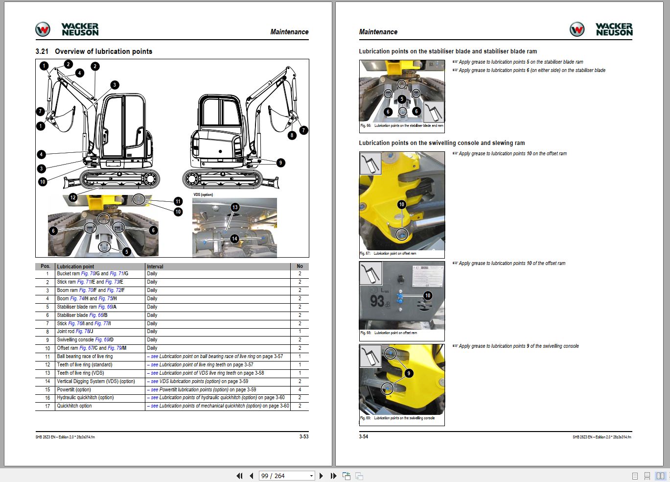
3.21 Overview of lubrication points
3.22 Cab
3.23 Electrical system
3.24 General maintenance work
3.25 Preparatory work before taking out of service
3.26 Maintenance if the machine is out of service for a longer period of time
3.27 Fire extinguisher
4 Engine
4.1 3TNV76-NNS engine overview
4.2 Fuel system
4.3 Cooling system
4.4 Checking and adjusting valve clearance
4.5 Tightening order for cylinder head bolts
4.6 Checking the injection nozzles
4.7 Checking the nozzle jet
4.8 Injection time
4.9 Removing and installing the injection pump
4.10 Measuring and adjusting the engine speed
4.11 Compression
4.12 Checking the coolant thermostat
4.13 Checking the thermal switch
4.14 Oil pressure switch
4.15 Checking the coolant circuit
4.16 Cleaning the cooling water channels
4.17 Coolant and fuel hoses
4.18 Crankcase vent
4.19 Replacing the glow plugs
4.20 Engine trouble
5 Hydraulic system
5.1 Hydraulic pump PVD-0B-23BP-8G3-5083A
5.2 Main valve block
5.3 Drive counterbalancing system
5.4 Regeneration – stick section
5.5 Bucket pre-tension
5.6 Auxiliary hydraulics flow rate adjustment
5.7 Travelling drive
5.8 Swivel unit
5.9 Swivel joint
5.10 Swivel joint VDS (option)
5.11 Pilot valves
5.12 Changeover valve for SAE/ISO controls (option)
5.13 Proportional valve (option)
5.14 Changeover valve VDS (option)
5.15 3/2 directional valve (option)
5.16 Easy Lock valve (option)
5.17 Hydraulic oil tank service valve (option)
5.18 Breather filter
5.19 Auxiliary hydraulics connections
5.20 Troubleshooting in the hydraulic system
5.21 Hydraulics diagram (legend)
5.22 Hydraulics diagram 28Z3
5.23 Hydraulics diagram for options 28Z3
5.24 Main valve block diagram 28Z3
6 Electrical system
6.1 Ohm's Law (current, voltage, resistance); power
6.2 Measuring equipment, measuring methods
6.3 Cable colour coding
6.4 Relays
6.5 Socket
6.6 Electric units
6.7 Fuse box
6.8 Alternator
6.9 Starter
6.10 Switches: overview
6.11 Cigarette lighter
6.12 Radio and mounting/wiring for radio installation (option)
6.13 Front working light
6.14 Cab lights (option)
6.15 Rotating beacon (option)
6.16 Driving signal (option)
6.17 Wiring diagram (legend)
6.18 Wiring diagram
6.19 Engine/chassis wiring harness (legend)
6.20 Chassis/engine wiring harness
6.21 Cab wiring harness
6.22 Proportional controls wiring harness (option)
6.23 Engine speed control wiring harness (option)
6.24 Driving signal wiring harness (option)
6.25 Hydraulic quickhitch wiring harness (option)
6.26 Battery lead
7 Options
7.1 Counterweight
7.2 Long stick
7.3 Automatic engine speed setting
7.4 Grab pipework
7.5 3rd control circuit/PowerTilt ports
7.6 Safe load indicator
7.7 Safe load indicator DE (from serial no. AG04828) (safety valves for boom)
7.8 Safe load indicator FR (from serial no. AG04828) (safety valves for boom, stick and stabiliser blade)
7.9 Hose burst valve safety feature
7.10 Mechanical quickhitch
7.11 Hydraulic quickhitch (Easy Lock)
7.12 3rd control circuit
7.13 Drive interlock (antitheft protection)
7.14 Proportional controls
7.15 Engine oil service valve
8 PowerTilt PTS06
8.1 General instructions
8.2 Tools
8.3 Separating the bucket or equipment from the PowerTilt swivel device
8.4 Separating the PowerTilt swivel device from the machine
8.5 Exploded views PTS06
8.6 Assembly drawing
8.7 Removing the standard journal coupling
8.8 Removing the end cap, securing ring and internal decompression valve
8.9 Removing the shaft
8.10 Removing the piston tube body
8.11 Removing the seals (kit A), shaft bearings and pressure discs (kit B)
8.12 Checking components and dead centre marks
8.13 Trial assembly
8.14 Installing the seals (kit A), shaft bearings and pressure discs (kit B)
8.15 Installing the piston tube
8.16 Installing the shaft
8.17 Installing the end cap and the securing ring
8.18 Installing the internal decompression valve
8.19 Installing the standard journal coupling
8.20 Lubrication and tests
8.21 Securing the PowerTilt swivel device on the machine
8.22 Fitting a bucket or equipment onto the PowerTilt swivel device
8.23 Troubleshooting
8.24 Adjusting the play on the PowerTilt


Size: 25.97 MB
Format: PDF
Language: English
Brand: Wacker Neuson
Type of Machine: Excavator
Type of Manual: Service Manual, Electrical and Hydraulic Diagram
Model: Wacker Neuson s 28Z3 Excavator
Part Number: Wacker Neuson Excavators 28Z3 Service Manual and Diagram 1000178347
Publication Date: 2011
Number of Pages: 264 Pages
Contents:
1 Operation
1.1 Notices on this service manual
1.2 Identification of warnings and dangers
1.3 Designated use and exemption from liability
1.4 Type labels and component numbers
1.5 Machine overview
1.6 Cab overview
1.7 Cab (legend)
1.8 Instrument panel overview
1.9 Instrument panel legend
1.10 Overview of open engine and valve compartment
1.11 Engine compartment: overview
1.12 Chassis overview
1.13 Valve compartment
1.14 Stop and park the machine
2 Specifications
2.1 Chassis
2.2 Engine
2.3 Hydraulic system
2.4 Undercarriage and swivel unit
2.5 Stabiliser blade
2.6 Electrical system
2.7 Noise levels
2.8 Vibration
2.9 Coolant compound table
2.10 Powertilt
2.11 Model-specific tightening torques
2.12 General tightening torques
2.13 Dimensions model 28Z3
2.14 Dimensions model 28Z3 VDS
2.15 Lift capacity table 28Z3 (short stick)
2.16 Lift capacity table 28Z3 long stick (option)
2.17 Lift capacity table 28Z3 short stick and extra weight (option)
2.18 Lift capacity table 28Z3 long stick (option) and extra weight (option)
2.19 Lift capacity table 28Z3 VDS (short stick)
2.20 Lift capacity table 28Z3 long stick VDS (option)
2.21 Kinematics
3 Maintenance
3.1 Fluids and lubricants
3.2 Maintenance label
3.3 Maintenance plan (overview)
3.4 Service package
3.5 Introduction
3.6 Safety-relevant parts
3.7 Fuel system
3.8 Engine lubrication system
3.9 Engine and hydraulics cooling system
3.10 Air filter
3.11 Change cab air filter
3.12 V-belt
3.13 Pressure check
3.14 Test report
3.15 Hydraulic system
3.16 Pilot valve
3.17 Travelling drive
3.18 Tracks
3.19 Maintenance of attachments
3.20 Lubrication points
3.21 Overview of lubrication points
3.22 Cab
3.23 Electrical system
3.24 General maintenance work
3.25 Preparatory work before taking out of service
3.26 Maintenance if the machine is out of service for a longer period of time
3.27 Fire extinguisher
4 Engine
4.1 3TNV76-NNS engine overview
4.2 Fuel system
4.3 Cooling system
4.4 Checking and adjusting valve clearance
4.5 Tightening order for cylinder head bolts
4.6 Checking the injection nozzles
4.7 Checking the nozzle jet
4.8 Injection time
4.9 Removing and installing the injection pump
4.10 Measuring and adjusting the engine speed
4.11 Compression
4.12 Checking the coolant thermostat
4.13 Checking the thermal switch
4.14 Oil pressure switch
4.15 Checking the coolant circuit
4.16 Cleaning the cooling water channels
4.17 Coolant and fuel hoses
4.18 Crankcase vent
4.19 Replacing the glow plugs
4.20 Engine trouble
5 Hydraulic system
5.1 Hydraulic pump PVD-0B-23BP-8G3-5083A
5.2 Main valve block
5.3 Drive counterbalancing system
5.4 Regeneration – stick section
5.5 Bucket pre-tension
5.6 Auxiliary hydraulics flow rate adjustment
5.7 Travelling drive
5.8 Swivel unit
5.9 Swivel joint
5.10 Swivel joint VDS (option)
5.11 Pilot valves
5.12 Changeover valve for SAE/ISO controls (option)
5.13 Proportional valve (option)
5.14 Changeover valve VDS (option)
5.15 3/2 directional valve (option)
5.16 Easy Lock valve (option)
5.17 Hydraulic oil tank service valve (option)
5.18 Breather filter
5.19 Auxiliary hydraulics connections
5.20 Troubleshooting in the hydraulic system
5.21 Hydraulics diagram (legend)
5.22 Hydraulics diagram 28Z3
5.23 Hydraulics diagram for options 28Z3
5.24 Main valve block diagram 28Z3
6 Electrical system
6.1 Ohm's Law (current, voltage, resistance); power
6.2 Measuring equipment, measuring methods
6.3 Cable colour coding
6.4 Relays
6.5 Socket
6.6 Electric units
6.7 Fuse box
6.8 Alternator
6.9 Starter
6.10 Switches: overview
6.11 Cigarette lighter
6.12 Radio and mounting/wiring for radio installation (option)
6.13 Front working light
6.14 Cab lights (option)
6.15 Rotating beacon (option)
6.16 Driving signal (option)
6.17 Wiring diagram (legend)
6.18 Wiring diagram
6.19 Engine/chassis wiring harness (legend)
6.20 Chassis/engine wiring harness
6.21 Cab wiring harness
6.22 Proportional controls wiring harness (option)
6.23 Engine speed control wiring harness (option)
6.24 Driving signal wiring harness (option)
6.25 Hydraulic quickhitch wiring harness (option)
6.26 Battery lead
7 Options
7.1 Counterweight
7.2 Long stick
7.3 Automatic engine speed setting
7.4 Grab pipework
7.5 3rd control circuit/PowerTilt ports
7.6 Safe load indicator
7.7 Safe load indicator DE (from serial no. AG04828) (safety valves for boom)
7.8 Safe load indicator FR (from serial no. AG04828) (safety valves for boom, stick and stabiliser blade)
7.9 Hose burst valve safety feature
7.10 Mechanical quickhitch
7.11 Hydraulic quickhitch (Easy Lock)
7.12 3rd control circuit
7.13 Drive interlock (antitheft protection)
7.14 Proportional controls
7.15 Engine oil service valve
8 PowerTilt PTS06
8.1 General instructions
8.2 Tools
8.3 Separating the bucket or equipment from the PowerTilt swivel device
8.4 Separating the PowerTilt swivel device from the machine
8.5 Exploded views PTS06
8.6 Assembly drawing
8.7 Removing the standard journal coupling
8.8 Removing the end cap, securing ring and internal decompression valve
8.9 Removing the shaft
8.10 Removing the piston tube body
8.11 Removing the seals (kit A), shaft bearings and pressure discs (kit B)
8.12 Checking components and dead centre marks
8.13 Trial assembly
8.14 Installing the seals (kit A), shaft bearings and pressure discs (kit B)
8.15 Installing the piston tube
8.16 Installing the shaft
8.17 Installing the end cap and the securing ring
8.18 Installing the internal decompression valve
8.19 Installing the standard journal coupling
8.20 Lubrication and tests
8.21 Securing the PowerTilt swivel device on the machine
8.22 Fitting a bucket or equipment onto the PowerTilt swivel device
8.23 Troubleshooting
8.24 Adjusting the play on the PowerTilt
More the random threads same category:
- Wacker Neuson 803 Spare Parts List
- Wacker Neuson Skid Steer Loader Track ST31 Error Codes, Service, Operator's & Parts Manual EN ES FR
- Wacker Neuson Crawler Excavator 3503 Spare Parts List_1000189534
- Wacker Neuson Compact Excavator 2503 3503 3003 3703 Service Manual_1000081433
- Wacker Neuson Reversible Vibratory Plates DPU 6555 H Operator, Repair Manual & Spare Parts Catalog
- Wacker Neuson Crawler Excavator EZ17 Spare Parts List_1000298089
- Wacker Neuson Skid Steer Loader Track ST35 Error Codes, Service, Operator's & Parts Manual EN DE FR
- Wacker Neuson Wheel Loaders 550 5055 5055L Spare Parts List_1000274206
- Wacker Neuson Track Excavator 6003 Service Manual_1000129840
- Wacker Neuson Track Excavators 75Z3, 8003 Operators Manual_1000132136
- Wacker Neuson Track Excavators 50Z3 Service Manual 1000129833
- Wacker Neuson Wheel Loaders 750, 850 Service Manual_1000183988
- Wacker Neuson Track Excavators 1404 Service Manual_1000166693
- Wacker Neuson Walk-Behind Trowels CT 36-5A Parts Manual_0009438
- Wacker Neuson Kramer Wheel Loader 1150 Spare Parts Manual_100018445