
Raymond Automation 3030 Maintenance Manual 1312900001A 2019
- Download this document, you need 750 Gallons
Raymond Automation 3030 Maintenance Manual 1312900001A 2019
Size: 20.33 MB
Format: PDF
Language: English
Brand: Raymond
Type of Machine: Automation, Stacker Trucks
Type of Manual: Maintenance Manual, Electrical Schematic
Model: Raymond Courier 3030 Stacker Trucks
Serial Number: 303-18-00001 and Up
Part Number: 1312900001A
Issue Date: 2019
Number of Pages: 431 Pages
Contents:
Document Revision History
Service Information Documents List
Section 1. How To Use This Manual
Manual Design
Interactive Electronic Technical Manuals
Abbreviations & Symbols
Section 2. Safety
Definitions
General Safety
Battery Safety
Jacking Safety
Tie-Down for Transport
Towing
Static Safety
Welding Safety
Section 3. Systems Overview
Introduction
Truck Model Identification
Lift Truck Specifications
Special Tools
Operator Display and Programming
Automated Truck
Graphical Operator Interface (GOI)
Guidance System Overview
FlashWare
Section 4. Scheduled Maintenance
Maintenance Guidelines
Initial 90 Day/250 Deadman Hours (HD) Maintenance
Every 180 Days or 500 Deadman Hours
Every 360 Days or 2000 Deadman Hours (HD)
Contactor Tip Inspection
Chain Maintenance
Fork Inspection
Section 5. Troubleshooting
How to Use This Section
Electrical Troubleshooting Guidelines
Fuses
DC Electric Motors
AC Electric Motors
Hydraulic Troubleshooting Guidelines
Symptom Tables: Lift/Lower System
Symptom Tables: Travel (Forward/Reverse) System
Symptom Tables: Wiring System
Symptom Tables: Guidance System
Section 6. Messages and Codes
List of Messages and Codes
Traction Amplifier LED Diagnostics
Traction Amplifier Flash Codes
Caution and Error Codes
Message and Caution Codes
Error Codes
GOI Message Reference
Section 7. Component Procedures
List of Component Procedures by Truck System
Component Locator Photos
Steering and Controls
Drive and Brake
Electrical Components
Guidance System Components
Hydraulic Components
Mast, Chain, Hose, Cable
Options
Section 8. Theory of Operation
Definitions
Traction System
Lift/Lower System
Theory of Operation - Electric Power Steering
Pinout Matrix
Section A. Appendix
Lubrication Equivalency Chart
Thread Adhesives, Sealants, and Lubricants
Component Specific Service/Torque Chart
Torque Chart - Standard (Ferrous)
Torque Chart - Standard (Brass)
Torque Chart - Metric (Ferrous)
Torque Chart - Metric (Brass)
Torque Chart - Thread Forming Screws
Torque Chart - Metric Thread-Forming Screws
Torque Chart - Hydraulic Fittings
Torque Chart - Straight Thread Face Seal O-Rings
Decimal Equivalent Chart
Standard/Metric Conversions
Section I. Index
Schematics
Figure 1. Model 3030 Automated Stacker Truck
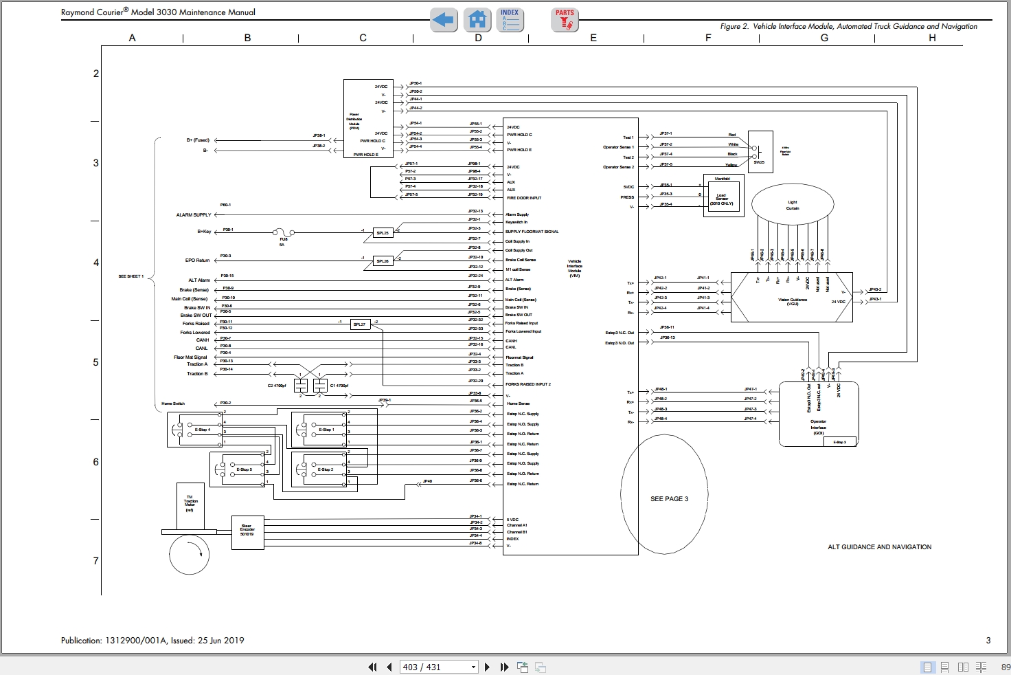
Figure 2. Vehicle Interface Module, Automated Truck Guidance and Navigation
Figure 3. Model 3030 Guidance and Navigation System (Continued)
Figure 4. Control Handle and Options
Figure 5. Component Legend (Page 1 of 2)
Figure 6. Component Legend (Page 2 of 2)
Figure 7. Power Distribution Diagram
Figure 8. Hydraulic Schematic
RSIs
Scheduled Maintenance - Software Updates
3030 Pallet Nested Switch Service Information
360 Day/2000 Hour Inspection – Power Steering Electrical Connectors
Energy Power System Power Source Limiting Option
New Keypad with Ribbon
New VSM Software 3.1.3
New Vehicle Manager Software Version 1.5
New VSM Software 3.0.3
Encrypted Wi-Fi Supplicant File Support
Scheduled Maintenance Information Update
Water Intrusion into Handle Head


Size: 20.33 MB
Format: PDF
Language: English
Brand: Raymond
Type of Machine: Automation, Stacker Trucks
Type of Manual: Maintenance Manual, Electrical Schematic
Model: Raymond Courier 3030 Stacker Trucks
Serial Number: 303-18-00001 and Up
Part Number: 1312900001A
Issue Date: 2019
Number of Pages: 431 Pages
Contents:
Document Revision History
Service Information Documents List
Section 1. How To Use This Manual
Manual Design
Interactive Electronic Technical Manuals
Abbreviations & Symbols
Section 2. Safety
Definitions
General Safety
Battery Safety
Jacking Safety
Tie-Down for Transport
Towing
Static Safety
Welding Safety
Section 3. Systems Overview
Introduction
Truck Model Identification
Lift Truck Specifications
Special Tools
Operator Display and Programming
Automated Truck
Graphical Operator Interface (GOI)
Guidance System Overview
FlashWare
Section 4. Scheduled Maintenance
Maintenance Guidelines
Initial 90 Day/250 Deadman Hours (HD) Maintenance
Every 180 Days or 500 Deadman Hours
Every 360 Days or 2000 Deadman Hours (HD)
Contactor Tip Inspection
Chain Maintenance
Fork Inspection
Section 5. Troubleshooting
How to Use This Section
Electrical Troubleshooting Guidelines
Fuses
DC Electric Motors
AC Electric Motors
Hydraulic Troubleshooting Guidelines
Symptom Tables: Lift/Lower System
Symptom Tables: Travel (Forward/Reverse) System
Symptom Tables: Wiring System
Symptom Tables: Guidance System
Section 6. Messages and Codes
List of Messages and Codes
Traction Amplifier LED Diagnostics
Traction Amplifier Flash Codes
Caution and Error Codes
Message and Caution Codes
Error Codes
GOI Message Reference
Section 7. Component Procedures
List of Component Procedures by Truck System
Component Locator Photos
Steering and Controls
Drive and Brake
Electrical Components
Guidance System Components
Hydraulic Components
Mast, Chain, Hose, Cable
Options
Section 8. Theory of Operation
Definitions
Traction System
Lift/Lower System
Theory of Operation - Electric Power Steering
Pinout Matrix
Section A. Appendix
Lubrication Equivalency Chart
Thread Adhesives, Sealants, and Lubricants
Component Specific Service/Torque Chart
Torque Chart - Standard (Ferrous)
Torque Chart - Standard (Brass)
Torque Chart - Metric (Ferrous)
Torque Chart - Metric (Brass)
Torque Chart - Thread Forming Screws
Torque Chart - Metric Thread-Forming Screws
Torque Chart - Hydraulic Fittings
Torque Chart - Straight Thread Face Seal O-Rings
Decimal Equivalent Chart
Standard/Metric Conversions
Section I. Index
Schematics
Figure 1. Model 3030 Automated Stacker Truck
Figure 2. Vehicle Interface Module, Automated Truck Guidance and Navigation
Figure 3. Model 3030 Guidance and Navigation System (Continued)
Figure 4. Control Handle and Options
Figure 5. Component Legend (Page 1 of 2)
Figure 6. Component Legend (Page 2 of 2)
Figure 7. Power Distribution Diagram
Figure 8. Hydraulic Schematic
RSIs
Scheduled Maintenance - Software Updates
3030 Pallet Nested Switch Service Information
360 Day/2000 Hour Inspection – Power Steering Electrical Connectors
Energy Power System Power Source Limiting Option
New Keypad with Ribbon
New VSM Software 3.1.3
New Vehicle Manager Software Version 1.5
New VSM Software 3.0.3
Encrypted Wi-Fi Supplicant File Support
Scheduled Maintenance Information Update
Water Intrusion into Handle Head
More the random threads same category:
- Raymond Pallet Truck 8210 Maintenance Parts Manual, Electrical Schematic
- Raymond Walkie RSS22-RSS30-RSS40 Maintenance Parts Manual, Electrical Schematic
- Raymond Pallet 8210 Parts Manual & Service Maintenance Manual
- Raymond Walkie 6210 Maintenance Parts Manual, Electrical Schematic
- Raymond EASi R30, R35, R40, R50 Lift Truck 1012609 Parts Catalog
- Raymond Walkie RAS20-25 Maintenance Parts Manual, Electrical Schematic
- Raymond EASi Reach-Forklift Truck ET-F.DT-F Schematics Manual
- Raymond Pallet Truck 8310 8410 8510 8610 Schematic, Maintenance & Parts Manual
- Raymond Reach Truck 20 SCR Maintenance Parts Manuals
- Raymond Reach Truck 7700-7720 Maintenance Parts Manual, Electrical Schematic
- Raymond 8300, 8400, 8500, 8600 Pallet Truck 59,749 & up Maintenance Manual
- Raymond Reach Truck 7200-7300-7310 Maintenance Parts Manual, Electrical Schematic
- Raymond Orderpicker 5200 Maintenance Parts Manual - Schematics
- Raymond EASi Reach-Forklift Truck EZ-D DC-D Schematics Manual
- Raymond 9600-9700 Swing-Reach Schematics Manual