Mitsubishi Outlander 2022 USA Circuit Diagrams
- Download this document, you need 1605 Gallons
Mitsubishi Outlander 2022 USA Circuit Diagrams
Size: 246 MB
Format: PDF
Language: English
Brand: Mitsubishi
Model: Mitsubishi Outlander 2022 USA
Date: 03-2021
No.: TSB-21-00-008
Contents:
Abbreviation List.pdf
New features.pdf
Specifications.pdf
TSB AC.pdf
TSB Engine perfomance.pdf
Circuit diagram\ACCESSORY POWER SUPPLY FUSE NO. 40.pdf
Circuit diagram\ACCESSORY POWER SUPPLY FUSE NO. 44.pdf
Circuit diagram\ACCESSORY POWER SUPPLY.pdf
Circuit diagram\ACCESSORY PRE-WIRE.pdf
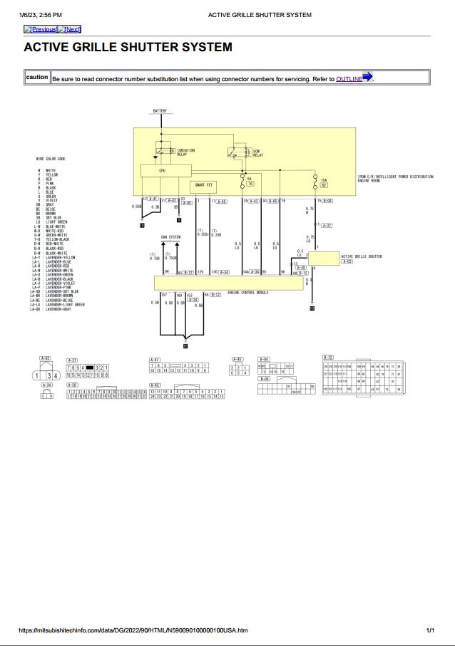
Circuit diagram\ACTIVE GRILLE SHUTTER SYSTEM.pdf
Circuit diagram\AUTO LIGHT SYSTEM.pdf
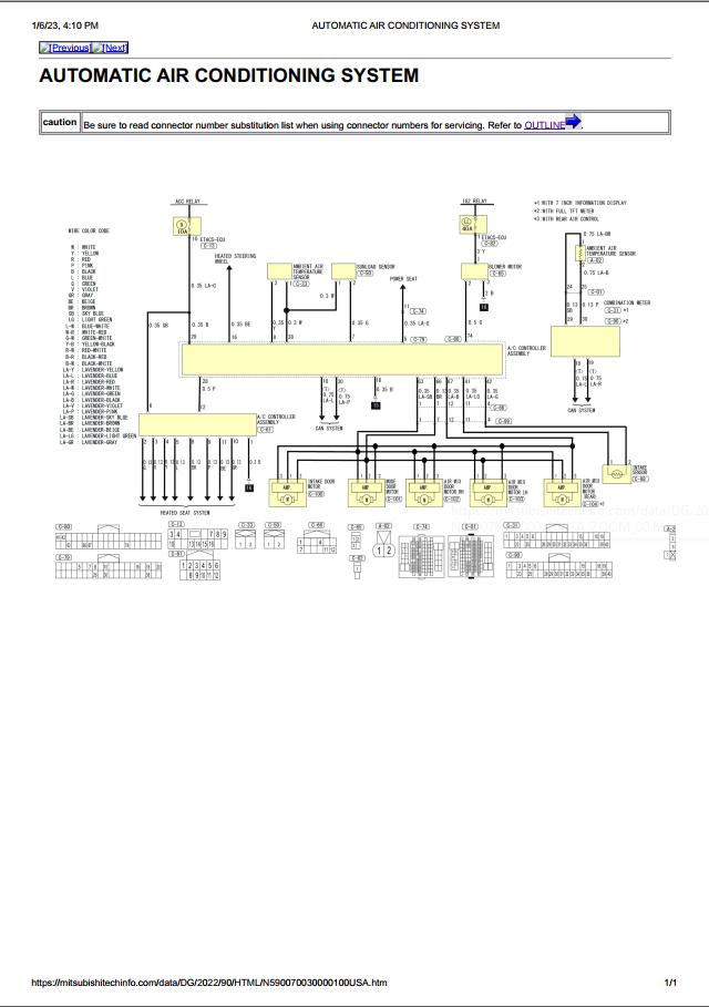
Circuit diagram\AUTOMATIC AIR CONDITIONING SYSTEM.pdf
Circuit diagram\AUTOMATIC DRIVE POSITIONER SYSTEM.pdf
Circuit diagram\AWD SYSTEM.pdf
Circuit diagram\BACKUP LIGHT.pdf
Circuit diagram\BATTERY POWER SUPPLY FUSE NO. 26.pdf
Circuit diagram\BCM (BODY CONTROL MODULE).pdf
Circuit diagram\BRAKE CONTROL SYSTEM.pdf
Circuit diagram\CAN GATEWAY SYSTEM.pdf
Circuit diagram\CAN SYSTEM.pdf
Circuit diagram\CHARGING SYSTEM.pdf
Circuit diagram\CHASSIS CONTROL SYSTEM.pdf
Circuit diagram\Connector Information.pdf
Circuit diagram\Connector Symbols.pdf
Circuit diagram\CVT CONTROL SYSTEM.pdf
Circuit diagram\DAYTIME RUNNING LIGHT SYSTEM.pdf
Circuit diagram\DOOR MIRROR.pdf
Circuit diagram\DRIVER ASSISTANCE SYSTEM.pdf
Circuit diagram\ELECTRIC PARKING BRAKE SYSTEM.pdf
Circuit diagram\ELECTRIC SHIFT CONTROL SYSTEM.pdf
Circuit diagram\ELECTRONICALLY CONTROLLED POWER STEERING SYSTEM.pdf
Circuit diagram\ENGINE CONTROL SYSTEM.pdf
Circuit diagram\FORWARD COLLISION MITIGATION SYSTEM (FCM).pdf
Circuit diagram\FRONT FOG LIGHT.pdf
Circuit diagram\FRONT WIPER AND WASHER SYSTEM.pdf
Circuit diagram\Fuse, Connector and Terminal Arrangement.pdf
Circuit diagram\Fuse, Fusible link, Relay box and Terminal Arrangement.pdf
Circuit diagram\Fuse, Relay, Connector and Terminal Arrangement.pdf
Circuit diagram\GROUND - BODY HARNESS.pdf
Circuit diagram\GROUND - ENGINE CONTROL HARNESS.pdf
Circuit diagram\GROUND - MAIN HARNESS.pdf
Circuit diagram\HEAD UP DISPLAY.pdf
Circuit diagram\HEADLIGHT.pdf
Circuit diagram\HEATED SEAT SYSTEM.pdf
Circuit diagram\HEATED STEERING WHEEL.pdf
Circuit diagram\HORN.pdf
Circuit diagram\IGNITION POWER SUPPLY FUSE NO. 24.pdf
Circuit diagram\IGNITION POWER SUPPLY FUSE NO. 79.pdf
Circuit diagram\IGNITION POWER SUPPLY FUSE NO. 9.pdf
Circuit diagram\IGNITION POWER SUPPLY.pdf
Circuit diagram\ILLUMINATION.pdf
Circuit diagram\IMMOBILIZER SYSTEM.pdf
Circuit diagram\INSIDE MIRROR.pdf
Circuit diagram\INTERIOR ROOM LIGHT CONTROL SYSTEM.pdf
Circuit diagram\IPDM E_R (INTELLIGENT POWER DISTRIBUTION MODULE ENGINE ROOM).pdf
Circuit diagram\KEYLESS OPERATION KEY_ENGINE START FUNCTION.pdf
Circuit diagram\KEYLESS OPERATION SYSTEM.pdf
Circuit diagram\M.U.T.-III SE CHECKING SYSTEM.pdf
Circuit diagram\METER (7 INCH INFORMATION DISPLAY METER).pdf
Circuit diagram\METER (FULL TFT METER).pdf
Circuit diagram\MI-PILOT Assist.pdf
Circuit diagram\MITSUBISHI CONNECT (WITH BOSE).pdf
Circuit diagram\MITSUBISHI CONNECT (WITHOUT BOSE).pdf
Circuit diagram\MULTI AROUND MONITOR SYSTEM.pdf
Circuit diagram\PARKING, LICENSE PLATE, SIDE MARKER AND TAIL LAMP.pdf
Circuit diagram\POWER DISTRIBUTION SYSTEM.pdf
Circuit diagram\POWER DOOR LOCK SYSTEM.pdf
Circuit diagram\POWER LIFTGATE SYSTEM.pdf
Circuit diagram\POWER SEAT SYSTEM FOR DRIVER SIDE - WITHOUT AUTOMATIC DRIVE POSITIONER.pdf
Circuit diagram\POWER SEAT SYSTEM FOR PASSENGER SIDE.pdf
Circuit diagram\POWER SOCKET.pdf
Circuit diagram\POWER WINDOW SYSTEM.pdf
Circuit diagram\REAR VIEW MONITOR SYSTEM.pdf
Circuit diagram\REAR WINDOW DEFOGGER.pdf
Circuit diagram\REAR WIPER AND WASHER SYSTEM.pdf
Circuit diagram\SEAT BELT WARNING SYSTEM.pdf
Circuit diagram\SONAR SYSTEM.pdf
Circuit diagram\SRS AIR BAG CONTROL SYSTEM.pdf
Circuit diagram\STARTING SYSTEM.pdf
Circuit diagram\STOP LAMP.pdf
Circuit diagram\SUNROOF SYSTEM.pdf
Circuit diagram\TELEMATICS SYSTEM.pdf
Circuit diagram\TIRE PRESSURE MONITORING SYSTEM.pdf
Circuit diagram\TURN SIGNAL AND HAZARD WARNING LAMP.pdf
Circuit diagram\USB CHARGE PORT.pdf
Circuit diagram\VEHICLE SECURITY SYSTEM.pdf
Circuit diagram\WARNING CHIME SYSTEM.pdf
Circuit diagram\WIRELESS CHARGER.pdf
LOCATION\A_C UNIT SUB HARNESS.pdf
LOCATION\BODY HARNESS.pdf
LOCATION\ENGINE CONTROL HARNESS.pdf
LOCATION\ENGINE ROOM HARNESS.pdf
LOCATION\FRONT DOOR LH HARNESS.pdf
LOCATION\FRONT DOOR RH HARNESS.pdf
LOCATION\FRONT SEAT HARNESS.pdf
LOCATION\LIFTGATE HARNESS.pdf
LOCATION\MAIN HARNESS.pdf
LOCATION\OUTLINE.pdf
LOCATION\REAR DOOR LH HARNESS.pdf
LOCATION\REAR DOOR RH HARNESS.pdf
LOCATION\ROOM LAMP HARNESS.pdf
manual\ABS\Component Parts Location.pdf
manual\ABS\CONSULT Function.pdf
manual\ABS\DTC Index.pdf
manual\ABS\Reference Value.pdf
manual\AC\A_C Compressor Control.pdf
manual\AC\Component Parts Location.pdf
manual\AC\Component Parts LocationPTC.pdf
manual\AC\Door Control.pdf
manual\AC\DTC Index.pdf
manual\AC\Exploded View Apmplifer.pdf
manual\AC\Exploded View pressure sensor.pdf
manual\AC\Fail-safe.pdf
manual\AC\Reference Valuedata list.pdf
manual\AC\Removal and Installation amplif.pdf
manual\AC\System Description.pdf
manual\AC\Temperature Control.pdf
manual\AT\Component Description.pdf
manual\AT\Component Parts Location.pdf
manual\AT\CONSULT Function Shift control.pdf
manual\AT\CONSULT Function.pdf
manual\AT\DTC Index.pdf
manual\AT\Electric Shift Control Module.pdf
manual\AT\Electric Shift Selector.pdf
manual\AT\Electric Shift Sensor.pdf
manual\AT\Reference Value.pdf
manual\AT\Shift Actuator.pdf
manual\AT\Shift system description.pdf
manual\AT\System Description.pdf
manual\AT\System Description1.pdf
manual\AT\TCM ECU.pdf
manual\BODY CONTROL SYSTEM\DTC Index.pdf
manual\BODY CONTROL SYSTEM\DTC Inspection Priority Chart.pdf
manual\BODY CONTROL SYSTEM\ECU pinout.reference value.pdf
manual\BODY CONTROL SYSTEM\Fail-safe.pdf
manual\BODY CONTROL SYSTEM\U1327-57.pdf
manual\BODY CONTROL SYSTEM\Work Procedure.pdf
manual\CAN\CAN Communication Control Circuit.pdf
manual\CAN\CAN Communication Signal Chart.pdf
manual\CAN\CAN System Specification Chart.pdf
manual\CAN\Component Parts Location.pdf
manual\CAN\Gateway Parts Location.pdf
manual\CAN\gateway removing.pdf
manual\CAN\Gateway system description.pdf
manual\CAN\Gateway.pdf
manual\CAN\Self-Diagnosis.pdf
manual\CAN\Symptom When Error Occurs in CAN Communication System.pdf
manual\CAN\System Description.pdf
manual\CAN\System Diagram.pdf
manual\Engine perfomance\ACC steering switch inspection.pdf
manual\Engine perfomance\AF sensor inspection.pdf
manual\Engine perfomance\APPS inspection.pdf
manual\Engine perfomance\ASCD steering switch inspection.pdf
manual\Engine perfomance\Component Inspection (Active Grille Shutter).pdf
manual\Engine perfomance\Component Parts Location.pdf
manual\Engine perfomance\CONSULT Function.pdf
manual\Engine perfomance\DTC C035C Description.pdf
manual\Engine perfomance\DTC Index.pdf
manual\Engine perfomance\ECM _ Exploded View.pdf
manual\Engine perfomance\ECU pinout.pdf
manual\Engine perfomance\ELECTRIC INTAKE VALVE TIMING CONTROL MODULE _ Exploded View.pdf
manual\Engine perfomance\EVAP Canister Vent Control Valve.pdf
manual\Engine perfomance\EVAP Canister.pdf
manual\Engine perfomance\EVAP system description.pdf
manual\Engine perfomance\Exhaust valve timingcontrol.syst.description.pdf
manual\Engine perfomance\Fuel pressure control syst.description.pdf
manual\Engine perfomance\Fuel rail pressure sensor inspect .pdf
manual\Engine perfomance\Fuel Tank Temperature Sensor.pdf
manual\Engine perfomance\Heated Oxygen Sensor 2.pdf
manual\Engine perfomance\High pressure fuel pump inspection.pdf
manual\Engine perfomance\High Pressure Fuel Pump.pdf
manual\Engine perfomance\IDLE SPEED _ Service Data.pdf
manual\Engine perfomance\IGNITION TIMING _ Service Data.pdf
manual\Engine perfomance\Intake manifold runner control valve inspect.pdf
manual\Engine perfomance\Intake Manifold Runner Control Valve.pdf
manual\Engine perfomance\Intake manifold tuning valve actuatorInspection.pdf
manual\Engine perfomance\Intake Manifold Tuning Valve.pdf
manual\Engine perfomance\Intake manifold tunning syst.description.pdf
manual\Engine perfomance\Intake valve timing control description.pdf
manual\Engine perfomance\Knock sensor inspection.pdf
manual\Engine perfomance\MAP sensor inspection.pdf
manual\Engine perfomance\MASS AIR FLOW SENSOR _ Service Data.pdf
manual\Engine perfomance\Mass air flow sensor insp.pdf
manual\Engine perfomance\Oil control system description.pdf
manual\Engine perfomance\Oil data reset.pdf
manual\Engine perfomance\Oil pressure control system.pdf
manual\Engine perfomance\Oxygen sensor heater inspection.pdf
manual\Engine perfomance\Positive Crankcase Ventilation.pdf
manual\Engine perfomance\Power generat.variable control descript.pdf
manual\Engine perfomance\Refrigerant Pressure Sensor.pdf
manual\Engine perfomance\System Description.pdf
manual\Engine perfomance\Test Value and Test Limit.pdf
manual\Engine perfomance\Values on the Diagnosis Tool.pdf
manual\Engine perfomance\Work Procedure.pdf
manual\IPDM E.R\DTC Index.pdf
manual\IPDM E.R\DTC Inspection Priority Chart.pdf
manual\IPDM E.R\ECU pinout.Reference Value.pdf
manual\IPDM E.R\Fail-safe.pdf
manual\Mirror\Disassembly and Assembly.pdf
manual\Mirror\Exploded View cover.pdf
manual\Mirror\Glass removing.pdf
manual\Mirror\Removal and Installation.pdf
manual\SRS\Component Parts Location set belt.pdf
manual\SRS\Component Parts Location.pdf
manual\SRS\Crash Zone Sensor.pdf
manual\SRS\Description.pdf
manual\SRS\DTC Index.pdf
manual\SRS\Occupant detection system control unit.pdf
manual\SRS\System Description.pdf
manual\SRS\Warning Lamp_Indicator Lamp.pdf
Size: 246 MB
Format: PDF
Language: English
Brand: Mitsubishi
Model: Mitsubishi Outlander 2022 USA
Date: 03-2021
No.: TSB-21-00-008
Contents:
Abbreviation List.pdf
New features.pdf
Specifications.pdf
TSB AC.pdf
TSB Engine perfomance.pdf
Circuit diagram\ACCESSORY POWER SUPPLY FUSE NO. 40.pdf
Circuit diagram\ACCESSORY POWER SUPPLY FUSE NO. 44.pdf
Circuit diagram\ACCESSORY POWER SUPPLY.pdf
Circuit diagram\ACCESSORY PRE-WIRE.pdf
Circuit diagram\ACTIVE GRILLE SHUTTER SYSTEM.pdf
Circuit diagram\AUTO LIGHT SYSTEM.pdf
Circuit diagram\AUTOMATIC AIR CONDITIONING SYSTEM.pdf
Circuit diagram\AUTOMATIC DRIVE POSITIONER SYSTEM.pdf
Circuit diagram\AWD SYSTEM.pdf
Circuit diagram\BACKUP LIGHT.pdf
Circuit diagram\BATTERY POWER SUPPLY FUSE NO. 26.pdf
Circuit diagram\BCM (BODY CONTROL MODULE).pdf
Circuit diagram\BRAKE CONTROL SYSTEM.pdf
Circuit diagram\CAN GATEWAY SYSTEM.pdf
Circuit diagram\CAN SYSTEM.pdf
Circuit diagram\CHARGING SYSTEM.pdf
Circuit diagram\CHASSIS CONTROL SYSTEM.pdf
Circuit diagram\Connector Information.pdf
Circuit diagram\Connector Symbols.pdf
Circuit diagram\CVT CONTROL SYSTEM.pdf
Circuit diagram\DAYTIME RUNNING LIGHT SYSTEM.pdf
Circuit diagram\DOOR MIRROR.pdf
Circuit diagram\DRIVER ASSISTANCE SYSTEM.pdf
Circuit diagram\ELECTRIC PARKING BRAKE SYSTEM.pdf
Circuit diagram\ELECTRIC SHIFT CONTROL SYSTEM.pdf
Circuit diagram\ELECTRONICALLY CONTROLLED POWER STEERING SYSTEM.pdf
Circuit diagram\ENGINE CONTROL SYSTEM.pdf
Circuit diagram\FORWARD COLLISION MITIGATION SYSTEM (FCM).pdf
Circuit diagram\FRONT FOG LIGHT.pdf
Circuit diagram\FRONT WIPER AND WASHER SYSTEM.pdf
Circuit diagram\Fuse, Connector and Terminal Arrangement.pdf
Circuit diagram\Fuse, Fusible link, Relay box and Terminal Arrangement.pdf
Circuit diagram\Fuse, Relay, Connector and Terminal Arrangement.pdf
Circuit diagram\GROUND - BODY HARNESS.pdf
Circuit diagram\GROUND - ENGINE CONTROL HARNESS.pdf
Circuit diagram\GROUND - MAIN HARNESS.pdf
Circuit diagram\HEAD UP DISPLAY.pdf
Circuit diagram\HEADLIGHT.pdf
Circuit diagram\HEATED SEAT SYSTEM.pdf
Circuit diagram\HEATED STEERING WHEEL.pdf
Circuit diagram\HORN.pdf
Circuit diagram\IGNITION POWER SUPPLY FUSE NO. 24.pdf
Circuit diagram\IGNITION POWER SUPPLY FUSE NO. 79.pdf
Circuit diagram\IGNITION POWER SUPPLY FUSE NO. 9.pdf
Circuit diagram\IGNITION POWER SUPPLY.pdf
Circuit diagram\ILLUMINATION.pdf
Circuit diagram\IMMOBILIZER SYSTEM.pdf
Circuit diagram\INSIDE MIRROR.pdf
Circuit diagram\INTERIOR ROOM LIGHT CONTROL SYSTEM.pdf
Circuit diagram\IPDM E_R (INTELLIGENT POWER DISTRIBUTION MODULE ENGINE ROOM).pdf
Circuit diagram\KEYLESS OPERATION KEY_ENGINE START FUNCTION.pdf
Circuit diagram\KEYLESS OPERATION SYSTEM.pdf
Circuit diagram\M.U.T.-III SE CHECKING SYSTEM.pdf
Circuit diagram\METER (7 INCH INFORMATION DISPLAY METER).pdf
Circuit diagram\METER (FULL TFT METER).pdf
Circuit diagram\MI-PILOT Assist.pdf
Circuit diagram\MITSUBISHI CONNECT (WITH BOSE).pdf
Circuit diagram\MITSUBISHI CONNECT (WITHOUT BOSE).pdf
Circuit diagram\MULTI AROUND MONITOR SYSTEM.pdf
Circuit diagram\PARKING, LICENSE PLATE, SIDE MARKER AND TAIL LAMP.pdf
Circuit diagram\POWER DISTRIBUTION SYSTEM.pdf
Circuit diagram\POWER DOOR LOCK SYSTEM.pdf
Circuit diagram\POWER LIFTGATE SYSTEM.pdf
Circuit diagram\POWER SEAT SYSTEM FOR DRIVER SIDE - WITHOUT AUTOMATIC DRIVE POSITIONER.pdf
Circuit diagram\POWER SEAT SYSTEM FOR PASSENGER SIDE.pdf
Circuit diagram\POWER SOCKET.pdf
Circuit diagram\POWER WINDOW SYSTEM.pdf
Circuit diagram\REAR VIEW MONITOR SYSTEM.pdf
Circuit diagram\REAR WINDOW DEFOGGER.pdf
Circuit diagram\REAR WIPER AND WASHER SYSTEM.pdf
Circuit diagram\SEAT BELT WARNING SYSTEM.pdf
Circuit diagram\SONAR SYSTEM.pdf
Circuit diagram\SRS AIR BAG CONTROL SYSTEM.pdf
Circuit diagram\STARTING SYSTEM.pdf
Circuit diagram\STOP LAMP.pdf
Circuit diagram\SUNROOF SYSTEM.pdf
Circuit diagram\TELEMATICS SYSTEM.pdf
Circuit diagram\TIRE PRESSURE MONITORING SYSTEM.pdf
Circuit diagram\TURN SIGNAL AND HAZARD WARNING LAMP.pdf
Circuit diagram\USB CHARGE PORT.pdf
Circuit diagram\VEHICLE SECURITY SYSTEM.pdf
Circuit diagram\WARNING CHIME SYSTEM.pdf
Circuit diagram\WIRELESS CHARGER.pdf
LOCATION\A_C UNIT SUB HARNESS.pdf
LOCATION\BODY HARNESS.pdf
LOCATION\ENGINE CONTROL HARNESS.pdf
LOCATION\ENGINE ROOM HARNESS.pdf
LOCATION\FRONT DOOR LH HARNESS.pdf
LOCATION\FRONT DOOR RH HARNESS.pdf
LOCATION\FRONT SEAT HARNESS.pdf
LOCATION\LIFTGATE HARNESS.pdf
LOCATION\MAIN HARNESS.pdf
LOCATION\OUTLINE.pdf
LOCATION\REAR DOOR LH HARNESS.pdf
LOCATION\REAR DOOR RH HARNESS.pdf
LOCATION\ROOM LAMP HARNESS.pdf
manual\ABS\Component Parts Location.pdf
manual\ABS\CONSULT Function.pdf
manual\ABS\DTC Index.pdf
manual\ABS\Reference Value.pdf
manual\AC\A_C Compressor Control.pdf
manual\AC\Component Parts Location.pdf
manual\AC\Component Parts LocationPTC.pdf
manual\AC\Door Control.pdf
manual\AC\DTC Index.pdf
manual\AC\Exploded View Apmplifer.pdf
manual\AC\Exploded View pressure sensor.pdf
manual\AC\Fail-safe.pdf
manual\AC\Reference Valuedata list.pdf
manual\AC\Removal and Installation amplif.pdf
manual\AC\System Description.pdf
manual\AC\Temperature Control.pdf
manual\AT\Component Description.pdf
manual\AT\Component Parts Location.pdf
manual\AT\CONSULT Function Shift control.pdf
manual\AT\CONSULT Function.pdf
manual\AT\DTC Index.pdf
manual\AT\Electric Shift Control Module.pdf
manual\AT\Electric Shift Selector.pdf
manual\AT\Electric Shift Sensor.pdf
manual\AT\Reference Value.pdf
manual\AT\Shift Actuator.pdf
manual\AT\Shift system description.pdf
manual\AT\System Description.pdf
manual\AT\System Description1.pdf
manual\AT\TCM ECU.pdf
manual\BODY CONTROL SYSTEM\DTC Index.pdf
manual\BODY CONTROL SYSTEM\DTC Inspection Priority Chart.pdf
manual\BODY CONTROL SYSTEM\ECU pinout.reference value.pdf
manual\BODY CONTROL SYSTEM\Fail-safe.pdf
manual\BODY CONTROL SYSTEM\U1327-57.pdf
manual\BODY CONTROL SYSTEM\Work Procedure.pdf
manual\CAN\CAN Communication Control Circuit.pdf
manual\CAN\CAN Communication Signal Chart.pdf
manual\CAN\CAN System Specification Chart.pdf
manual\CAN\Component Parts Location.pdf
manual\CAN\Gateway Parts Location.pdf
manual\CAN\gateway removing.pdf
manual\CAN\Gateway system description.pdf
manual\CAN\Gateway.pdf
manual\CAN\Self-Diagnosis.pdf
manual\CAN\Symptom When Error Occurs in CAN Communication System.pdf
manual\CAN\System Description.pdf
manual\CAN\System Diagram.pdf
manual\Engine perfomance\ACC steering switch inspection.pdf
manual\Engine perfomance\AF sensor inspection.pdf
manual\Engine perfomance\APPS inspection.pdf
manual\Engine perfomance\ASCD steering switch inspection.pdf
manual\Engine perfomance\Component Inspection (Active Grille Shutter).pdf
manual\Engine perfomance\Component Parts Location.pdf
manual\Engine perfomance\CONSULT Function.pdf
manual\Engine perfomance\DTC C035C Description.pdf
manual\Engine perfomance\DTC Index.pdf
manual\Engine perfomance\ECM _ Exploded View.pdf
manual\Engine perfomance\ECU pinout.pdf
manual\Engine perfomance\ELECTRIC INTAKE VALVE TIMING CONTROL MODULE _ Exploded View.pdf
manual\Engine perfomance\EVAP Canister Vent Control Valve.pdf
manual\Engine perfomance\EVAP Canister.pdf
manual\Engine perfomance\EVAP system description.pdf
manual\Engine perfomance\Exhaust valve timingcontrol.syst.description.pdf
manual\Engine perfomance\Fuel pressure control syst.description.pdf
manual\Engine perfomance\Fuel rail pressure sensor inspect .pdf
manual\Engine perfomance\Fuel Tank Temperature Sensor.pdf
manual\Engine perfomance\Heated Oxygen Sensor 2.pdf
manual\Engine perfomance\High pressure fuel pump inspection.pdf
manual\Engine perfomance\High Pressure Fuel Pump.pdf
manual\Engine perfomance\IDLE SPEED _ Service Data.pdf
manual\Engine perfomance\IGNITION TIMING _ Service Data.pdf
manual\Engine perfomance\Intake manifold runner control valve inspect.pdf
manual\Engine perfomance\Intake Manifold Runner Control Valve.pdf
manual\Engine perfomance\Intake manifold tuning valve actuatorInspection.pdf
manual\Engine perfomance\Intake Manifold Tuning Valve.pdf
manual\Engine perfomance\Intake manifold tunning syst.description.pdf
manual\Engine perfomance\Intake valve timing control description.pdf
manual\Engine perfomance\Knock sensor inspection.pdf
manual\Engine perfomance\MAP sensor inspection.pdf
manual\Engine perfomance\MASS AIR FLOW SENSOR _ Service Data.pdf
manual\Engine perfomance\Mass air flow sensor insp.pdf
manual\Engine perfomance\Oil control system description.pdf
manual\Engine perfomance\Oil data reset.pdf
manual\Engine perfomance\Oil pressure control system.pdf
manual\Engine perfomance\Oxygen sensor heater inspection.pdf
manual\Engine perfomance\Positive Crankcase Ventilation.pdf
manual\Engine perfomance\Power generat.variable control descript.pdf
manual\Engine perfomance\Refrigerant Pressure Sensor.pdf
manual\Engine perfomance\System Description.pdf
manual\Engine perfomance\Test Value and Test Limit.pdf
manual\Engine perfomance\Values on the Diagnosis Tool.pdf
manual\Engine perfomance\Work Procedure.pdf
manual\IPDM E.R\DTC Index.pdf
manual\IPDM E.R\DTC Inspection Priority Chart.pdf
manual\IPDM E.R\ECU pinout.Reference Value.pdf
manual\IPDM E.R\Fail-safe.pdf
manual\Mirror\Disassembly and Assembly.pdf
manual\Mirror\Exploded View cover.pdf
manual\Mirror\Glass removing.pdf
manual\Mirror\Removal and Installation.pdf
manual\SRS\Component Parts Location set belt.pdf
manual\SRS\Component Parts Location.pdf
manual\SRS\Crash Zone Sensor.pdf
manual\SRS\Description.pdf
manual\SRS\DTC Index.pdf
manual\SRS\Occupant detection system control unit.pdf
manual\SRS\System Description.pdf
manual\SRS\Warning Lamp_Indicator Lamp.pdf
More the random threads same category:
- Mitsubishi 4G15 Engine Manual
- Mitsubishi L200 2015 Service Manual CD (Triton)
- Mitsubishi Canter Engine 4M51 Workshop Manual Rus
- Mitsubishi Canter 4D34T3 Diesel Engine Shop Manual
- Mitsubishi ASX 2011 Workshop Manual
- Mitsubishi L200 2005 Wiring Diagram
- Mitsubishi Pajero 2001-2006 Service Manual
- Mitsubishi L200 2012 Workshop Manual
- Mitsubishi Mirage 2015 Workshop Manual
- Mitsubishi Pajero 2011 Workshop Manual
- Mitsubishi ASX 2015 Service Manual CD
- Mitsubishi Outlander 2007 Owner Manual
- Mitsubishi Canter URO3 For Australia Shop Manual Electrical
- Mitsubishi L200 Pinout Engine ECU engine 4D56
- Mitsubishi Colt 2004 Wiring Diagram