

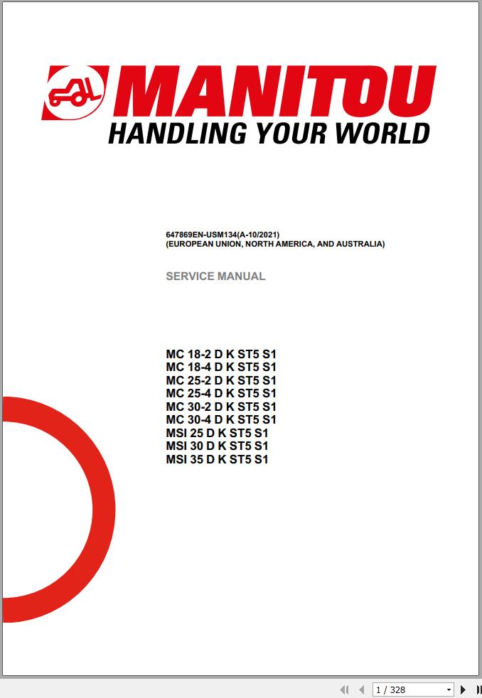
Manitou MC 18-2 D K ST5 S1 to MSI 35 D K ST5 S1 Service Manual 647869EN-USM134
- Download this document, you need 4400 Gallons
Manitou MC 18-2 D K ST5 S1 to MSI 35 D K ST5 S1 Service Manual 647869EN-USM134
Size: 31.95 MB
Format: PDF
Language: English
Brand: Manitou
Type of Machine: Forklift
Type of Manual: Service Manual, Electric and Hydraulic Diagram
Model: Manitou
MC 18-2 D K ST5 S1
MC 18-4 D K ST5 S1
MC 25-2 D K ST5 S1
MC 25-4 D K ST5 S1
MC 30-2 D K ST5 S1
MC 30-4 D K ST5 S1
MSI 25 D K ST5 S1
MSI 30 D K ST5 S1
MSI 35 D K ST5 S1
Part Number: 647869EN-USM134
Publication Date: 2021
Number of Pages: 328 Pages
Contents:
Legal disclaimer
Foreword
Intervention during the warranty period
Supplier Documentation List
Safety
Characteristics and specifications
Characteristics and specifications
Characteristics and specifications
Default Management on the Bauser Screen
Diagnostics Codes (Kubota 1803-CR-E5B)
Diagnostics Codes After Treatment (Kubota 1803-CR-E5B)
Diagnostics component
Size: 31.95 MB
Format: PDF
Language: English
Brand: Manitou
Type of Machine: Forklift
Type of Manual: Service Manual, Electric and Hydraulic Diagram
Model: Manitou
MC 18-2 D K ST5 S1
MC 18-4 D K ST5 S1
MC 25-2 D K ST5 S1
MC 25-4 D K ST5 S1
MC 30-2 D K ST5 S1
MC 30-4 D K ST5 S1
MSI 25 D K ST5 S1
MSI 30 D K ST5 S1
MSI 35 D K ST5 S1
Part Number: 647869EN-USM134
Publication Date: 2021
Number of Pages: 328 Pages
Contents:
Legal disclaimer
Foreword
Intervention during the warranty period
Supplier Documentation List
Safety
Servicing Rules
Machine Service OperationsServicing position
Preparation and safety instructions
Characteristics and specificationsTechnical datasheet MC 18-2 ST5
Designation
Weight
Running carriage
Dimensions
Performance parameters
Engines
Miscellaneous
Dimensional diagram
Technical datasheet MC 18-4 ST5
Designation
Weight
Running carriage
Dimensions
Performance parameters
Engines
Miscellaneous
Dimensional diagram
Technical datasheet MC 25-2 D K ST5 S1
Designation
Weight
Running carriage
Dimensions
Performance parameters
Engines
Miscellaneous
Dimensional diagram
Technical datasheet MC 25-4 D K ST5 S1
Designation
Weight
Running carriage
Dimensions
Performance parameters
Engines
Miscellaneous
Dimensional diagram
Technical datasheet MC 30-2 D K ST5 S1
Designation
Weight
Running carriage
Dimensions
Performance parameters
Engines
Miscellaneous
Dimensional diagram
Technical datasheet MC 30-4 D K ST5 S1
Designation
Weight
Running carriage
Dimensions
Performance parameters
Engines
Miscellaneous
Dimensional diagram
Technical datasheet MSI 25 D K ST5 S1
Designation
Weight
Running carriage
Dimensions
Performance parameters
Engines
Miscellaneous
Dimensional diagram
Technical datasheet MSI 30 D K ST5 S1
Designation
Weight
Running carriage
Dimensions
Performance parameters
Engines
Miscellaneous
Dimensional diagram
Technical datasheet MSI 35 D K ST5 S1
Designation
Weight
Running carriage
Dimensions
Performance parameters
Engines
Miscellaneous
Dimensional diagram
Lubricants & Fuels
Engine
Mast
Hydraulics
Overhead guard
Rear Axle (MC in 2W / MSI)
Rear Axle (MC in 4W)
Oil
Grease
Liquid
LocationLocation of name and identification plate
Location of name and identification plates
Reference InformationExplanation of symbols
List of Abbreviations
Standard tightening torques
Metric - imperial unit conversion
List of reference service manuals - EngineCharacteristics and specifications
Specifications D1803-CR-E5 - 26 kW
Specifications D1803-CR-TE5 - 36 kW
Locationengine component location 26 kW
Location of engine elements 26 kW
engine component location 36 kW
Location of engine elements 36 kW
air intake location 26 kW
Engine 26 kW
air intake location 36 kW
Engine 36 kW
exhaust location 26 kW
Engine 26 kW
exhaust location 36 kW
Engine 36 kW
Water circuit Engine location 26 kW
Engine 26 kW
Water circuit Engine location 36 kW
Engine 36 kW
Fuel circuit Location 26 kW
Engine 26 kW
Fuel circuit Location 36 kW
Engine 36 kW
Control and adjustmentcooling check - 26 kW
Fan control – 26 kW
cooling check - 36 kW
Fan control – 36 kW
Engine suspension adjustment
Tightening torque
Installation drawing
alternator belt tension adjustment
Alternator belt tension adjustment
RemovalDPF removal (26 kW)
Exhaust outlet tube
Outlet tube
DPF attachment
Exhaust outlet tube
Connection on the DPF
Pressure sensor
Counterweight cross member
Removal of the DPF
Removal DPF (36 kW)
Outlet pipe clamp
FAP pipe attachment
Sensor
Manifold outlet pipe
Reinforcement lug
Exhaust pipe support
FAP removal
Remove the alternator belt (26Kw)
Alternator pivot screw
Alternator tension screw
Belt routing
Remove the alternator belt (36kW)
Turbo hose
Alternator tension screw
Alternator pivot screw
Belt routing
Engine removal (26 kW)
Cooling hose
Changing the oil
Upper cooling hose
Cooler openings
Cooler fasteners
Disengage the cooler
Cooler removal
Diesel filters
ECU connectors
Cooling reservoir hose
Filter support fasteners
Diesel fuel filter support assembly
Fuse box lid
captive nut
Fuse box
Diagnostics plug
Engine ECU
Air filter
Engine ECU ground
Engine ECU and air filter assembly
Injector
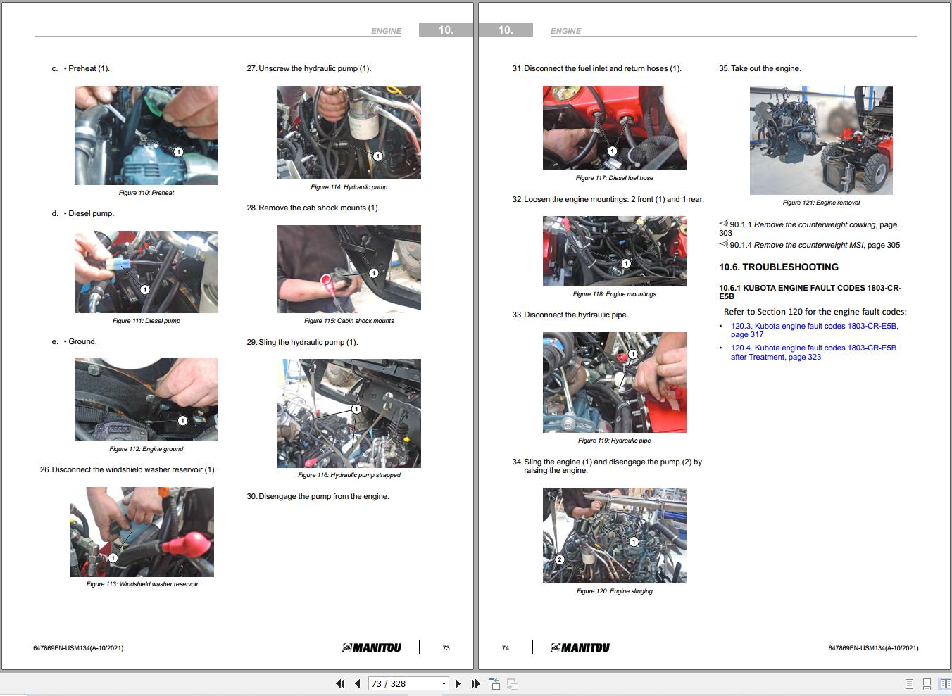
Preheat
Connector XC1
Alternator
Starter
Diesel fuel hose
Windshield washer reservoir
Hydraulic pump
Cab shock mount
Strap on the hydraulic pump
Engine shock mount
Sling on the engine
Hydraulic coupling
Disconnect the pump from the engine
Engine ground
Engine removed
Remove the motor (36 kW)
Radiator lower plate
Lower hose
Drain hose
Drip plate
Cooling and water return hose
Air hose
ECU harness and clamp
Cooling reservoir hose
Diesel fuel filters
Expansion tank support bracket
Expansion tank support bracket
SPU computer
Fuse box cover
Fuse box
Diagnostics plug
Air filter clogging
ECU and air filter support bracket
ECU and air filter support bracket assembly
Cooler fastener
cooler disengaged
Cooler on the ground
Manifold outlet
Engine sensors
FAP support
Alternator
Engine connector
Preheat
Diesel pump
Engine ground
Windshield washer reservoir
Hydraulic pump
Cabin shock mounts
Hydraulic pump strapped
Diesel fuel hose
Engine mountings
Hydraulic pipe
Engine slinging
Engine removal
TroubleshootingEngine Diagnostic Codes (Refer to Section 120)
Engine Troubleshooting Details
Specific toolsElectronic belt tensiometer
Electronic belt tensiometer
List of reference service manuals - EngineCharacteristics and specifications
HYDROSTATIC PUMP A4VG CHARACTERISTICS
HYDROSTATIC PUMP A4VG 40 DA1D7/32R - 52556872
View of the pump
Technical file
Hydraulic diagram of the pump
Location of pump components
HYDROSTATIC PUMP A4VG 71 DA1D7 - 52596962
View of the pump
Technical file
Hydraulic diagram of the pump
Location of pump components
HYDRAULIC WHEEL MOTOR - MS05 - 52600979
Hydraulic wheel motor MS05
Hydraulic diagram — Hydraulic wheel motor MS05
HYDRAULIC WHEEL MOTOR - MSE05 - 52577970
HYDRAULIC WHEEL MOTOR MSE05
Hydraulic diagram — Hydraulic wheel motor MSE05
HYDRAULIC WHEEL MOTOR - MG02 / MGE02 - 52536697
Hydraulic wheel motor MG02 / MGE02
Hydraulic diagram — Hydraulic wheel motor MG02 / MGE02
2 WHEEL DRIVE HYDROSTATIC TRANSMISSION BLOCK - 52600350
2-wheel drive hydrostatic transmission block
General characteristics — 2-wheel drive hydrostatic transmission block
Hydraulic diagram — 2-wheel drive hydrostatic transmission block
Input/Output detail — 2-wheel drive hydrostatic transmission block
4 WHEEL DRIVE HYDROSTATIC TRANSMISSION BLOCK - 52541454
4-wheel drive hydrostatic transmission block
Hydraulic diagram— 4-wheel drive hydrostatic transmission block
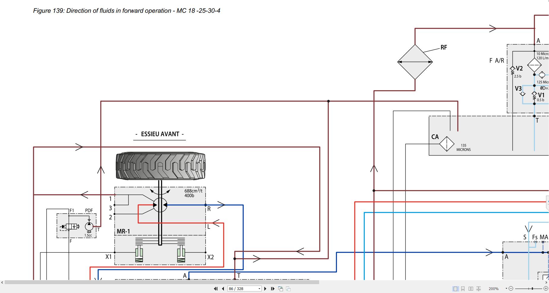
SchematicsFORWARD OPERATION FLUID DIRECTION - MC 18-25-30-4WD
Direction of fluids in forward operation - MC 18 -25-30-4
FORWARD OPERATION FLUID DIRECTION - MSI 25-30-35
Direction of fluids in forward operation - MSI 25-30-35
LocationTRANSMISSION COMPONENTS LOCATION MC -2
HYDROSTATIC SYSTEM MC18-2
TRANSMISSION COMPONENTS LOCATION MC -4
HYDROSTATIC SYSTEM MC18-4
TRANSMISSION COMPONENTS LOCATION MSI
MSI hydrostatic system
Control and adjustmentTIGHTENING TORQUE
Front wheel motor
Rear wheel motor
Engine / transmission flange
Engine / transmission flange
Measuring, checking and adjusting pump A4VG 56 DA
Pump A4VG 56 DA
Pump calibration
HP relief valve check
HP relief valve calibration
RemovalREMOVING THE FRONT WHEEL MOTOR
Wheel removal
Removal of hoses
Speed sensor
Fasteners
Wheel motor removal
REMOVING THE REAR WHEEL MOTOR
Removal of the rear wheel motor
REMOVING THE HYDROSTATIC PUMP
Slinging the hydrostatic pump
Hydrostatic pump fasteners
RefitHydrostatic pump REFIT
Hydrostatic pump refit
Front wheel engine REFIT
Wheel motor fasteners
Wheel nuts
Rear wheel engine REFIT
Rear wheel motor refit
Specific toolsBasic manometer kit
Basic manometer box — overview
Digital manometer kit
Digital manometer box
HYDROMATIK KIT (REPLACEMENT - A4VG-DA PUMP / A6VM MOTOR)
Hydromatik kit
Kit composition
TH7 VALVE HOSE AND CONNECTOR
Hose (TH7 by-pass valve)
Coupling (TH7 valve hose union fitting)
TH7 valve by-pass, consisting of:
Control and adjustmentAdjusting the stops on the rear axle (4WD)
Rear axle central hoses
Rear axle left motor stop screw
Measurement of dimension on rear axle cylinder rod
Min. clearance between the hoses and the rear axle cylinder rod
Rear axle left locknut and stop screw
Measurement of dimension on rear axle cylinder rod
Min. clearance between the hoses and the rear axle cylinder rod
TIGHTENING TORQUE 2WD
2-wheel drive rear axle
TIGHTENING TORQUE 4WD
Rear axle tightening torque, 4-wheel drive
PRE STRESSING THE SPINDLE BEARINGS: 2 WHEEL DRIVE
Direction of the force on the spindle bearing
TURNING RADII: 2 WHEEL DRIVE
2-wheel drive turning radii
TURNING RADII: 4 WHEEL DRIVE
4-wheel drive turning radii
RefitSECURE THE CONNECTING RODS
CASE No. 1: THE SPINDLE OR THE WHEEL MOTOR ENTERS BETWEEN THE 2 CONNECTING RODS
Shimming of connecting rods, case 1
CASE No. 2: THE WHEEL MOTOR HITS THE LOWER CONNECTING ROD
Shimming of connecting rods, case 2
CASE No. 3: THE WHEEL MOTOR HITS THE UPPER CONNECTING ROD
Shimming of connecting rods, case 3
Section Not ApplicableCharacteristics and specifications
Table - Double mast specifications
Table - Triple mast specifications
SchematicsDVT masts
View of mast assembly - New Mast DVT 3T
TLL masts
View of mast assembly - New Mast TLL 3T
TSLL masts
View of mast assembly - New Mast TSLL 3T
Control and adjustmentAdjust lifting cylinder - New mast 3T
Adjustment of lifting cylinder clearance
Tightening torques for mast chain - New Mast 3T
3 T mast chain tightening torque
Adjust mast lift rollers - New Mast 3T
Positioning of the roller to adjust its radial clearance
Positioning of the roller to adjust its axial clearance
Addition of shims on an inner mast roller
DVT masts
Adjust fork carriage support rollers - New Mast DVT 3T
RemovalRemove the central lifting cylinder
Slinging of the fork carriage
Hose guide block
Guide rollers
Cylinder head nut
Free lift cylinder
Rigid tubular support
Free lift cylinder hydraulic coupling
Retaining lug
Lower mounting screw
Cylinder removal
Tilt the mast to the ground
Tilt of the mast
Slinging the mast
Hydraulic couplings
Tilting cylinder pin
Tilting cylinder pin
Mast inclined to the floor
Remove the free lift mast
Slinging the mast
Disconnection of the hydraulic couplings from the mast
Unscrewing the tilting cylinder head pins
Disengagement of the tilting cylinder head pins
Removal of the mast’s lower half-clamps
Raising the mast
Mast resting on the ground
Remove the lateral lifting cylinder
Cylinder head fastener
Tube retaining tie
Cylinder upper fastener
Lower hydraulic coupling
Lower retaining nut
Cylinder head to be disengaged
Cylinder removal
Remove the inner jamb
Connection of hoses
Hose retaining lug
Interior upright removed
Hydraulic pipe
Lifting chains
Free lift hydraulic pipe
Lower stop
Upper guide rollers
Lower guide rollers
Pulley support
Chain rollers
Disengagement of the interior upright
DLL masts
Tilt the mast to the ground
Remove the free lift cylinder
RefitMast chain assembly (New Mast) - 3T
Orientation of the chain fastener pins
Opening angle of chain fastener pins
Bending back of chain fastener pins
Axial clearance of the chain plates
Assembly of the chain tensioners to the mast
Characteristics and specificationsList of Data Sheets for Hydraulic Components
SDM100 hydraulic valve block
SDM100 hydraulic valve bank
General characteristics — SDM100 hydraulic valve bank
Details of inlets/outlets — SDM100 hydraulic valve bank
Wiring diagram — SDM100 hydraulic valve bank
Electrical values — SDM100 hydraulic valve bank
2D views — SDM100 hydraulic valve bank
Details of elements — SDM100 hydraulic valve bank
Hydraulic diagram — SDM100 hydraulic valve bank
SDM100 hydraulic valve block - JSM
SDM100 hydraulic valve bank - JSM
General characteristics — SDM100 hydraulic valve bank - JSM
Details of inlets/outlets — SDM100 hydraulic valve bank - JSM
2D views — SDM100 hydraulic valve bank - JSM
Details of elements — SDM100 hydraulic valve bank - JSM
Hydraulic diagram — SDM100 hydraulic valve bank - JSM
Steering pump/Steering unit ospc 160 ls
3D diagram of steering pump/steering block
Hydraulic diagram of steering pump/steering block
Color key for steering pump operating principle diagrams
Steering pump schematic diagram – left turn
Schematic diagram of steering pump – resistance on a wheel
Schematic diagram of steering pump – full lock
PARKER 13 cm3 hydraulic pump
Hydraulic pump 13 cm3
Hydraulic diagram — Hydraulic pump 13 cm3
Input/Output detail — 13 cm3 hydraulic pump
General characteristics — Hydraulic pump 13 cm3
Working pressures — Hydraulic pump 13 cm3
HYDRAULIC PUMP 21 cm3
21 cm3 gear-driven hydraulic pump
Hydraulic diagram — 21 cm3 gear-driven hydraulic pump
Input/Output detail — 21 cm3 gear-driven hydraulic pump
General characteristics — 21 cm3 gear-driven hydraulic pump
Working pressures — 21 cm3 gear-driven hydraulic pump
Operation of the ECS option
Easy Connect system option
Hydraulic diagram — ECS Option
SchematicsHydraulic Schematic MC18-2
Hydraulic diagram MC18–2
Hydraulic Schematic MC18-4
Hydraulic diagram MC18–4
Hydraulic Schematic MC25-30-2
Hydraulic diagram MC25–30–2
Hydraulic Schematic MC25-30-4
Hydraulic diagram MC25–30–4
Hydraulic Schematic MSI25-30-35
Hydraulic diagram MSI25–30–35
LocationHydraulic local MC 18-25-30-2WD
Hydraulic location MC 18-25-30-2
Hydraulic local MC 18-25-30-4WD
Hydraulic location MC 18-25-30-4
Hydraulic local MSI 25-30-35
Hydraulics location MSI 25-30-35
Specific toolsDigital manometer kit
Digital manometer box
Basic manometer kit
Basic manometer box — overview
Characteristics and specificationsFusibles et Relais
Fuses and Relays
Entrées/Sorties Calculateurs
Main controller input/output SPU 40-26
Dashboard Module Bauser (MSI MC ST5)
Fiches techniques des composants électriques
electrical table TDS
Ignition switch
Air filter clogging
Front horn
FUEL LEVEL GAGE
JSM
BMEP
EMERGENCY STOP
SchematicsFunctional Organization (MSI MC ST5)
Key
Schematic diagram of operation (MSI MC ST5)
Position by Schematics - MSI MC ST5 Version PC
Schematics electrical MSI MC ST5 - Version PC
Diagram 1 - Starting
Diagram 1 - Starting
Diagram 2 - CAN Networks
Diagram 2 - CAN Networks
Diagram 3 - Transmission
Diagram 3 - Transmission
Diagram 4 - Hydraulic movements
Diagram 4 - Hydraulic movements
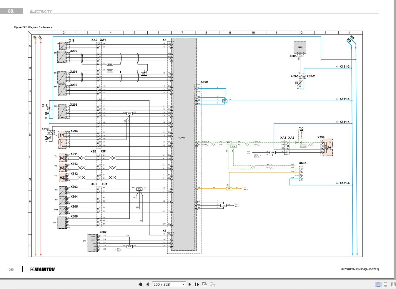
Diagram 5 - Sensors
Diagram 5 - Sensors
Diagram 6 - Ventilation and wipers
Diagram 6 - Ventilation and wipers
Diagram 7 - Options
Diagram 8 - Lights and signals
Diagram 8 - Lights and signals
Position by Schematic - MSI MC ST5 Version CAB
Schematics electrical MSI MC ST5 - Version CAB
Diagram 1 - Starting
Diagram 1 - Starting
Diagram 2 - CAN Networks
Diagram 2 - CAN Networks
Diagram 3 - Transmission
Diagram 3 - Transmission
Diagram 4 - Hydraulic movements
Diagram 4 - Hydraulic movements
Diagram 5 - Sensors
Diagram 5 - Sensors
Diagram 6 - Ventilation, air conditioning and wipers
Diagram 6 - Ventilation, air conditioning and wipers
Diagram 7 - Options
Diagram 7 - Options
Diagram 8 - Lights and signals
Diagram 8 - Lights and signals
Position by Schematic - MSI MC ST5 Version JSM
Schematics electrical MSI MC ST5 - Version JSM
Diagram 1 - Starting
Diagram 1 - Starting
Diagram 2 - CAN Networks
Diagram 2 - CAN Networks
Diagram 3 - Transmission
Diagram 3 - Transmission
Diagram 4 - Hydraulic movements
Diagram 4 - Hydraulic movements
Diagram 5 - Sensors
Diagram 5 - Sensors
Diagram 6 - Ventilation, air conditioning and wipers
Diagram 6 - Ventilation, air conditioning and wipers
Diagram 7 - Options
Diagram 7 - Options
Diagram 8 - Lights and signals
Diagram 8 - Lights and signals
LocationLocalization harness
PC location
JSM location
CAB location
PC location
JSM location
CAB location
Control and adjustmentResetting the oil maintenance counter
Display reset button
Flow chart of oil counter reset
RemovalCalculator removal
Battery cut-off
Rear transversal fastener
ECU connectors
Front fastener of the ECU
ECU removal
TroubleshootingDiagnostic Codes (Refer to Section 120)
Specific toolsSolenoid adapter
Electrovalve adapter
Breakout boxes
Breakout boxes
Control and adjustmentCalibrate the pedals
Dashboard
General menu
CAL1 menu: accelerator calibration
RemovalLifting the operator station
Sling loading/lifting rings
Slinging the guard on the mast
Guard shock mounts
Driver's seat switches
Valve bank lever cover
Tilting lever with pressure on the seat
Raising the cabin
Sling loading/lifting rings
Cab slinging
Cabin shock mounts
Valve bank cover
Tilt of the mast
RemovalRemoval of counterweight grille
Counterweight cowling
Rear spotlight connection
Removal air inlet on counterweight (26 kW)
Air intake hose clamps
Air intake hose
Counterweight removal (26 kW)
Exhaust and filter support fasteners
Sling loading/lifting rings
Wheel flaps
Counterweight lower attachment
Rear attachment
Counterweight slinging
Lifting the counterweight
Remove the counterweight (36 kW)
Rain cap
Rain cap support
Air filter hose
Outlet hose
filter support cross member
3-point slinging
Counterweight fasteners
Counterweight rear attachments
Counterweight removal
Section Not ApplicableDefault Management on the Bauser Screen
Fault display format
Reporting of a fault on the display
Display error counter
1st fault code display
1st fault code display
Machine Error CodesDiagnostics Codes (Kubota 1803-CR-E5B)
Diagnostics Codes After Treatment (Kubota 1803-CR-E5B)
Diagnostics component
Component diagnostics box
Example of connection to the component
Diagnostics caseDiagnostics case
Example of connection to the machine
Accessories
More the random threads same category:
- Manitou Telehandler MLT-X 735 120 LSU Repair Manual
- Manitou MVT 1130L - 1340L Repair manual
- Manitou MLT 741 120 LSU POWERSHIFT Repair Manual
- Manitou M50-4T Service Manual
- Manitou ALL MODEL FULL
- MANITOU MT732 SB E2 REPAIR MANUALS
- Manitou MLT 845, MLT-X 845 Service manual
- Manitou MRT 2540 Procedure to adjust the cable reel on the 3B6 system
- Manitou MT 1440 ST3B MT 1840 ST3B Operation Manual
- Manitou M30-2 Service manual
- Manitou MLT 845 Serie 3-E2 Service Manual
- Manitou MLT 630 T, 631 T, 731 T PS (225624 L) Hydraulic Shematic Diagram
- MANITOU MT732 MT 732 TURBO SERVICE MANUAL
- Manitou MLT 634 936088
- Manitou MRT 1530 Turbo Serie M 400 MOT 1104C 44T E2