Liebherr LTM1100-4.1 Carrier (LTM1090-3) UW-10 Part II Active Rear Axle Steering Service Manual
- Download this document, you need 1605 Gallons
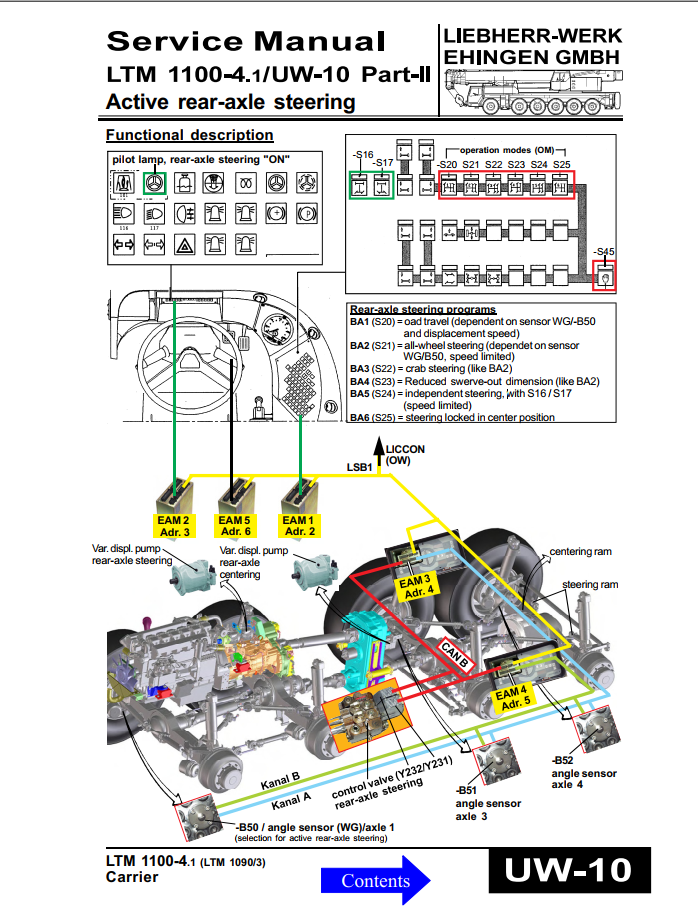
Liebherr LTM 1100-4.1 Carrier (LTM 1090-3) UW-10 Part II Active Rear Axle Steering Service Manual
Size: 10.6 MB
Format: PDF
Language: English
Type of Machine: Crane
Type of Document: Service Manual
Number of Pages: 71 pages
Model: Liebherr LTM 1100-4.1 Carrier (LTM 1090-3) UW-10
Contents:
Functional description - electricdhydrau lic
Hydraulic-system I
Functional outline for hydraulic system I .
Hydraulic-system Il
Functional outline for hydraulic system Il
Function hydraulic rear-axle centering
Function - centering ram (sectional view)
Functional diagram electric
Circuit diagram electric: Outline LSB I CAN
Circuit diagram electric: CAN-Bus
Circuit diagram electric: Control valves
Cicuit diagram electric: Angle sensors
Component overview
Angle sensors
Description and fitting location
Preparatory work
Fining of magnet
Fitting of sensor
Connection of sensor
Setting to zero of angle sensors
Setting into operation and dismantling
Functional test
Cicuit diagram of functional test
control block
Assembly indications and dismantling
Fitting and setting into operation
Steering centering rams
Assembly indications
Track adjustment
General
Test and adjustment
Indications
Rear-axle steering pump
Assembly indications
Checking and adjusting of stand-by-pressure and pressure cut-off
Checking and adjusting of load signal pressure
Centering pump
Assembly indications
Check and adjustment of pump pressure and stand-by pressure
Diaphragme accumulator
Assembly indications
Test programs
More the random threads same category:
- Liebherr Mobile Crane LTM 1080-1 Liccon Error Code
- Liebherr LTM-1090-4.1 Liccon Error Code
- Liebherr Mobile Crane LTM1090-2 Hydraulic Schematic
- Liebherr Mobile Crane LTM 1050-1 Service Manual
- Liebherr Mobile Crane LTM1200-5.1 Wiring Diagram
- Liebherr Mobile Crane LTM 1090-4.1,1100-4.1,1080-2 Wiring Diagram
- Liebherr LTM 1040-2.1 Service Manual
- Liebherr cranes service manuals
- Liebherr Data Bus and Liccon Computer System Technical Training
- Liebherr Crane LTM 1030-2 Service Manual Hydraulic
- Liebherr Mobile Crane LTM 1050 Diagrams Electrical
- Liebherr Mobile Crane LTM 1090-4.1 Hydraulic Schematic
- Liebherr LTM 1030-2 Service Manual Pneumatic
- Liebherr Mobile Crane LTM 1070-4.1 Spare Parts Catalogue
- Liebherr Mobile Crane LTM 1030-2.1 Wiring Diagram