
- Gallons
- 20,637
John Deere Telescopic Handlers 3215 3220 3415 3420 Diagnosis Tests Service Manual TM8108
- Download this document, you need 4400 Gallons
John Deere Telescopic Handlers 3215 3220 3415 3420 Diagnosis Tests Service Manual TM8108
Size: 55.2 MB
Language: English
Format: PDF
Type of Manual: Diagnosis and Tests Service Manual
Type of Machine: Telescopic Handlers
Model: John Deere 3215 3220 3415 3420 Telescopic Handlers
Part Number: TM8108
Number of Pages: 1403 Pages
Contents:
Foreword
Version Date
HYD - Diagnosis
HYD - Diagnosis
Engine
Tests and Troubleshooting
Fuel/Air Intake Systems - Tests
Air Intake System
Electrical System - General Information
General Information
Test Equipment
Electrical System – Tests (3215 and 3415) up to Serial No. 206800
Functional Schematics, Wiring and Harness Diagrams
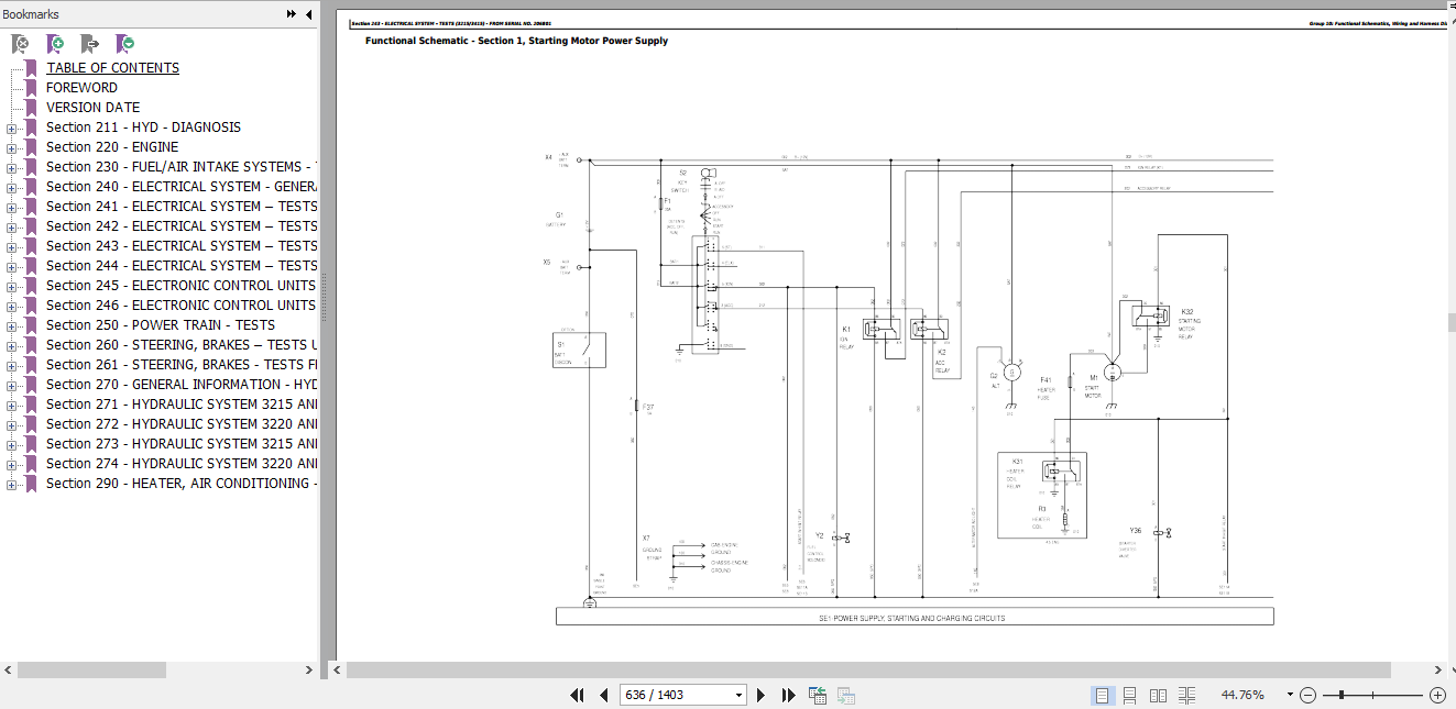
Section 1: Starting Motor Power Supply
Section 2: Seat Adjustment
Section 3: Wiper/Washer System
Section 4: Heater/Air Conditioning System
Section 5: Radio, Cab Interior Light and Horn
Section 6A: Lights (Region II)
Section 6B: Lights (North America)
Section 7: Reverse Travel Alarm, Cab Electrical Socket
Section 8: Instruments
Section 9: Forward Stability Indicator (Load Monitor)
Section 10: Steering Modes
Section 11A: Power Train, Shuttle Shift Transmission
Section 11B: Power Train, Power Shift Transmission
Section 12: Boom Control System
Section 13: Rear Auxiliary Hydraulic Functions
Section 14: Engine Control Unit
Load Indicator - Without Weighing Option (Not For NA)
Load Indicator - With Weighing Option (Not For NA)
Calibration of Weighing Device
Electrical System – Tests (3220 and 3420) up to Serial No. 206800
Functional Schematics, Wiring and Harness Diagrams
Section 1: Starting Motor Power Supply
Section 2: Seat Adjustment
Section 3: Wiper/Washer System
Section 4: Heater/Air Conditioning System
Section 5: Radio, Cab Interior Lighting and Horn
Section 6A: Lights (Region II)
Section 6B: Lights (North America)
Section 7: Reverse Travel Alarm, Cab Electrical Socket
Section 8: Instruments
Section 9: Forward Stability Indicator (Load Monitor)
Section 10: Steering Modes
Section 11A: Power Train, Shuttle Shift Transmission
Section 11B: Power Train, Power Shift Transmission
Section 12: Boom Control System
Section 13: Rear Auxiliary Hydraulic Functions
Section 14: Engine Control Unit
Electrical System – Tests (3215/3415) - from Serial No. 206801
Functional Schematics, Wiring and Harness Diagrams
Section 1: Starting Motor Power Supply
Section 2: Seat Adjustment
Section 3: Wiper/Washer System
Section 4: Heater/Air Conditioning System
Section 5: Radio, Cab Interior Light and Horn
Section 6A: Lights (Region II)
Section 7: Reverse Travel Alarm, Cab Electrical Socket
Section 8: Instruments
Section 9: Forward Stability Indicator (Load Monitor)
Section 10: Steering Modes
Section 11A: Power Train, Shuttle Shift Transmission
Section 11B: Power Train, Power Shift Transmission
Section 12: Boom Control System
Section 13: Rear Auxiliary Hydraulic Functions
Electrical System – Tests (3220/3420) - from Serial No. 206801
Functional Schematics, Wiring and Harness Diagrams
Section 1: Starting Motor Power Supply
Section 2: Seat Adjustment
Section 3: Wiper/Washer System
Section 4: Heater/Air Conditioning System
Section 5: Radio, Cab Interior Lighting and Horn
Section 6A: Lights (Region II)
Section 6B: Lights (North America)
Section 7: Reverse Travel Alarm, Cab Electrical Socket
Section 8: Instruments
Section 9: Forward Stability Indicator (Load Monitor)
Section 10: Steering Modes
Section 11A: Power Train, Shuttle Shift Transmission
Section 11B: Power Train, Power Shift Transmission
Section 12: Boom Control System
Section 13: Rear Auxiliary Hydraulic Functions
Section 14: Engine Control Unit
Electronic Control Units up to Serial No. 206800
ECU - Engine Control Unit (Level 12)
TCU - Transmission Control Unit
HYD - Hydraulic Control Unit
Load Indicator - Without Weighing Option (Not For NA)
Load Indicator - With Weighing Option (Not For NA)
Calibration of Weighing Device
Electronic Control Units from Serial No. 206801
Instrument Panel Adjustment from Serial No. 206801
ECU - Engine Control Unit (Level 12)
TCU - Transmission Control Unit
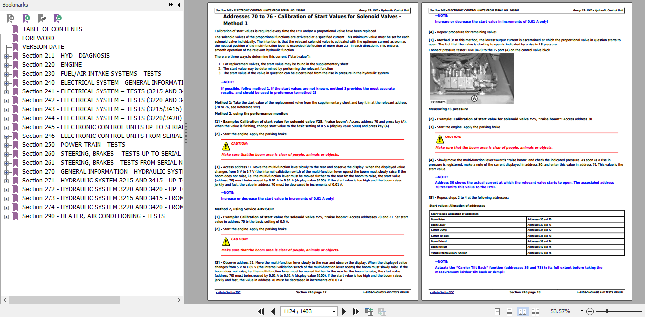
HYD - Hydraulic Control Unit
Load indicator, Setting from Serial No. 206801
Load Indicator - With Weighing Option from Serial No. 206801
Power Train - Tests
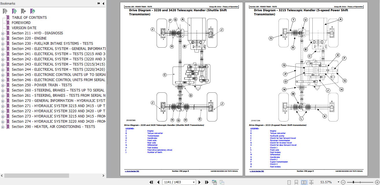
Drive - Theory of Operation
Torque Converter - Tests
Shuttle Shift Transmission - Tests
Power Shift Transmission - Tests
Shuttle Shift Transmission Diagnosis
Power Shift Transmission Diagnosis
Steering, Brakes – Tests up to Serial No. 206800
Brake System
Brake System Tests
Hydraulic Trailer Brake Valve
Steering System - Theory of Operation
Steering, Brakes - Tests from Serial No. 206801
Brake System from Serial No. 206801
Brake System Tests
Hydraulic Trailer Brake Valve
Steering System - Theory of Operation
Steering Test
Air Brake System
General Information - Hydraulic System
Valves - Theory of Operation
Hydraulic System 3215 and 3415 - up to Serial No. 206800
Hydraulic System - Hydraulic Circuit Diagram and Theory of Operation up to Serial No. 206800
Hydraulic System - Tests and Adjustments
Hydraulic System 3220 and 3420 - up to Serial No. 206800
Hydraulic System - Hydraulic Circuit Diagram and Theory of Operation up to Serial No. 206800
Hydraulic Pump - Operation, Tests and Adjustments
Hydraulic System - Tests
Hydraulic System 3215 and 3415 - from Serial No. 206801
Hydraulic System - Hydraulic Circuit Diagram and Theory of Operation from Serial No. 206801
Hydraulic System - Tests and Adjustments
Hydraulic System 3220 and 3420 - from Serial No. 206801
Hydraulic System - Hydraulic Circuit Diagram and Theory of Operation from Serial No. 206801
Hydraulic Pump - Operation, Tests and Adjustments
Hydraulic System - Tests
Heater, Air Conditioning - Tests
Theory of Operation
Tests
Size: 55.2 MB
Language: English
Format: PDF
Type of Manual: Diagnosis and Tests Service Manual
Type of Machine: Telescopic Handlers
Model: John Deere 3215 3220 3415 3420 Telescopic Handlers
Part Number: TM8108
Number of Pages: 1403 Pages
Contents:
Foreword
Version Date
HYD - Diagnosis
HYD - Diagnosis
Engine
Tests and Troubleshooting
Fuel/Air Intake Systems - Tests
Air Intake System
Electrical System - General Information
General Information
Test Equipment
Electrical System – Tests (3215 and 3415) up to Serial No. 206800
Functional Schematics, Wiring and Harness Diagrams
Section 1: Starting Motor Power Supply
Section 2: Seat Adjustment
Section 3: Wiper/Washer System
Section 4: Heater/Air Conditioning System
Section 5: Radio, Cab Interior Light and Horn
Section 6A: Lights (Region II)
Section 6B: Lights (North America)
Section 7: Reverse Travel Alarm, Cab Electrical Socket
Section 8: Instruments
Section 9: Forward Stability Indicator (Load Monitor)
Section 10: Steering Modes
Section 11A: Power Train, Shuttle Shift Transmission
Section 11B: Power Train, Power Shift Transmission
Section 12: Boom Control System
Section 13: Rear Auxiliary Hydraulic Functions
Section 14: Engine Control Unit
Load Indicator - Without Weighing Option (Not For NA)
Load Indicator - With Weighing Option (Not For NA)
Calibration of Weighing Device
Electrical System – Tests (3220 and 3420) up to Serial No. 206800
Functional Schematics, Wiring and Harness Diagrams
Section 1: Starting Motor Power Supply
Section 2: Seat Adjustment
Section 3: Wiper/Washer System
Section 4: Heater/Air Conditioning System
Section 5: Radio, Cab Interior Lighting and Horn
Section 6A: Lights (Region II)
Section 6B: Lights (North America)
Section 7: Reverse Travel Alarm, Cab Electrical Socket
Section 8: Instruments
Section 9: Forward Stability Indicator (Load Monitor)
Section 10: Steering Modes
Section 11A: Power Train, Shuttle Shift Transmission
Section 11B: Power Train, Power Shift Transmission
Section 12: Boom Control System
Section 13: Rear Auxiliary Hydraulic Functions
Section 14: Engine Control Unit
Electrical System – Tests (3215/3415) - from Serial No. 206801
Functional Schematics, Wiring and Harness Diagrams
Section 1: Starting Motor Power Supply
Section 2: Seat Adjustment
Section 3: Wiper/Washer System
Section 4: Heater/Air Conditioning System
Section 5: Radio, Cab Interior Light and Horn
Section 6A: Lights (Region II)
Section 7: Reverse Travel Alarm, Cab Electrical Socket
Section 8: Instruments
Section 9: Forward Stability Indicator (Load Monitor)
Section 10: Steering Modes
Section 11A: Power Train, Shuttle Shift Transmission
Section 11B: Power Train, Power Shift Transmission
Section 12: Boom Control System
Section 13: Rear Auxiliary Hydraulic Functions
Electrical System – Tests (3220/3420) - from Serial No. 206801
Functional Schematics, Wiring and Harness Diagrams
Section 1: Starting Motor Power Supply
Section 2: Seat Adjustment
Section 3: Wiper/Washer System
Section 4: Heater/Air Conditioning System
Section 5: Radio, Cab Interior Lighting and Horn
Section 6A: Lights (Region II)
Section 6B: Lights (North America)
Section 7: Reverse Travel Alarm, Cab Electrical Socket
Section 8: Instruments
Section 9: Forward Stability Indicator (Load Monitor)
Section 10: Steering Modes
Section 11A: Power Train, Shuttle Shift Transmission
Section 11B: Power Train, Power Shift Transmission
Section 12: Boom Control System
Section 13: Rear Auxiliary Hydraulic Functions
Section 14: Engine Control Unit
Electronic Control Units up to Serial No. 206800
ECU - Engine Control Unit (Level 12)
TCU - Transmission Control Unit
HYD - Hydraulic Control Unit
Load Indicator - Without Weighing Option (Not For NA)
Load Indicator - With Weighing Option (Not For NA)
Calibration of Weighing Device
Electronic Control Units from Serial No. 206801
Instrument Panel Adjustment from Serial No. 206801
ECU - Engine Control Unit (Level 12)
TCU - Transmission Control Unit
HYD - Hydraulic Control Unit
Load indicator, Setting from Serial No. 206801
Load Indicator - With Weighing Option from Serial No. 206801
Power Train - Tests
Drive - Theory of Operation
Torque Converter - Tests
Shuttle Shift Transmission - Tests
Power Shift Transmission - Tests
Shuttle Shift Transmission Diagnosis
Power Shift Transmission Diagnosis
Steering, Brakes – Tests up to Serial No. 206800
Brake System
Brake System Tests
Hydraulic Trailer Brake Valve
Steering System - Theory of Operation
Steering, Brakes - Tests from Serial No. 206801
Brake System from Serial No. 206801
Brake System Tests
Hydraulic Trailer Brake Valve
Steering System - Theory of Operation
Steering Test
Air Brake System
General Information - Hydraulic System
Valves - Theory of Operation
Hydraulic System 3215 and 3415 - up to Serial No. 206800
Hydraulic System - Hydraulic Circuit Diagram and Theory of Operation up to Serial No. 206800
Hydraulic System - Tests and Adjustments
Hydraulic System 3220 and 3420 - up to Serial No. 206800
Hydraulic System - Hydraulic Circuit Diagram and Theory of Operation up to Serial No. 206800
Hydraulic Pump - Operation, Tests and Adjustments
Hydraulic System - Tests
Hydraulic System 3215 and 3415 - from Serial No. 206801
Hydraulic System - Hydraulic Circuit Diagram and Theory of Operation from Serial No. 206801
Hydraulic System - Tests and Adjustments
Hydraulic System 3220 and 3420 - from Serial No. 206801
Hydraulic System - Hydraulic Circuit Diagram and Theory of Operation from Serial No. 206801
Hydraulic Pump - Operation, Tests and Adjustments
Hydraulic System - Tests
Heater, Air Conditioning - Tests
Theory of Operation
Tests
Last edited by a moderator:
More the random threads same category:
- John Deere 3800 Telescopic Handler Service Manuals
- John Deere Tractors 3030, 3130 Technical Manual_EN
- John Deere ZTrak Mower Z910A, Z920A, Z925A, Z930A, Z950A, Z960A, Z970A Technical Manual_TM109119 2012
- John Deere 9540 9560 9580 9640 9660 9680 WTS CWS Combines Repair Technical Manual EN TM4697
- John Deere Powershift Transmission DF180 Repair Technical Manual_EN
- John Deere 9540 9560 9580 9640 9660 9680 WTS CWS Combines Operator Manual_EN
- John Deere Sugarcane Harvester 3520 Parts Catalog_EN
- John Deere Backhoe Loader JD410 Maintenance Manual_EN
- John Deere 310SL HL, 410L Repair Technical Manual & Parts Catalog(2019)
- John Deere Tractors 1640, 1840, 2040, 2040 S Specifications & Special Tools Manual_EN
- John Deere Tractors 7600, 7700, 7800 Repair Manual_EN
- John Deere Powertech 4.5L-4045DFM50/TFM50-Marine Engines Part Catalog_EN
- John Deere Premium Tractors 6230, 6330, 6430, 6530 and 6630 Premium (European) Service Repair Manual
- John Deere 6090 Diesel Engine Component Technical Manual_CTM117719
- John Deere 3520 Sugar Cane Harvester Parts Catalog_EN