Hyster Forklift Claas 3 A3D9 (P2.0S-P2.5S-P3.0S Europe) Service Manual 03.2022
- Download this document, you need 2725 Gallons
Hyster Forklift Claas 3 A3D9 (P2.0S-P2.5S-P3.0S Europe) Service Manual 03.2022
Size: 56.6 MB
Format: PDF
Language: English
Brand: Hyster
Model: Hyster A3D9 P2.0S, P2.5S, P3.0S EU Service Manual 03.2022
Type of machine: Forklift Truck
Type of document: Service Manual
Content:
Important
General safety rules
Torque settings for screws nuts and fittings
Correct method for applying female fittings
Instruction for installing flexible hoses and fittings
Truck presentation
Views of the truck
Truck and load identification data
General specification
Traction wheel
Removal of the traction wheel
Torsion bar castor wheel assembly
Torsion bar castor wheel group disassembly
Replacement of the castor wheel torsion bar springs
Replacing the castor wheel
Replacing the castor wheel group
Load wheels
Replacing the tandem load wheel
Replacing the tandem load wheel assembly
Fixed linkage
Adjustable linkage
Removal of the linkage assembly
Key to tiller components
Tiller spring replacement
Adjustable steering spring replacement
Tiller removal
Replacement of the potentiometer and tiller base bearings
Replacement of the potentiometer and tiller base bearings of the adjustable steering
Key to scooter components
Scooter head removal
Scooter spring replacement
Replacement of the scooter control sensor and base bearings
Side gate replacement
Side gates microswitch replacement
Removal of the platform gas spring
Replacement of the platform touchless sensor
Removal of the platform
Replacement of the platform sensor
Traction motor
Motor dismantling
Steering motor
Steering motor dismantling
Forks chassis removal
Removal of the reduction unit
Disassembly of the reduction unit
Braking System
Removal of the electromagnetic brake
Before Installation
Truck assembly
Topping up the oil reservoir
Installation of the battery with vertical extraction
Installation of the battery with lateral extraction
Connection of cables to battery
List and description of the settings and adjustments to be carried out
Description of controller connectors
Device properties
Monitor menu
Troubleshooting
Warnings
Diagnosis system for F4-A Controller
Diagnosis system for Integrated Steering System
Electrical component measurements
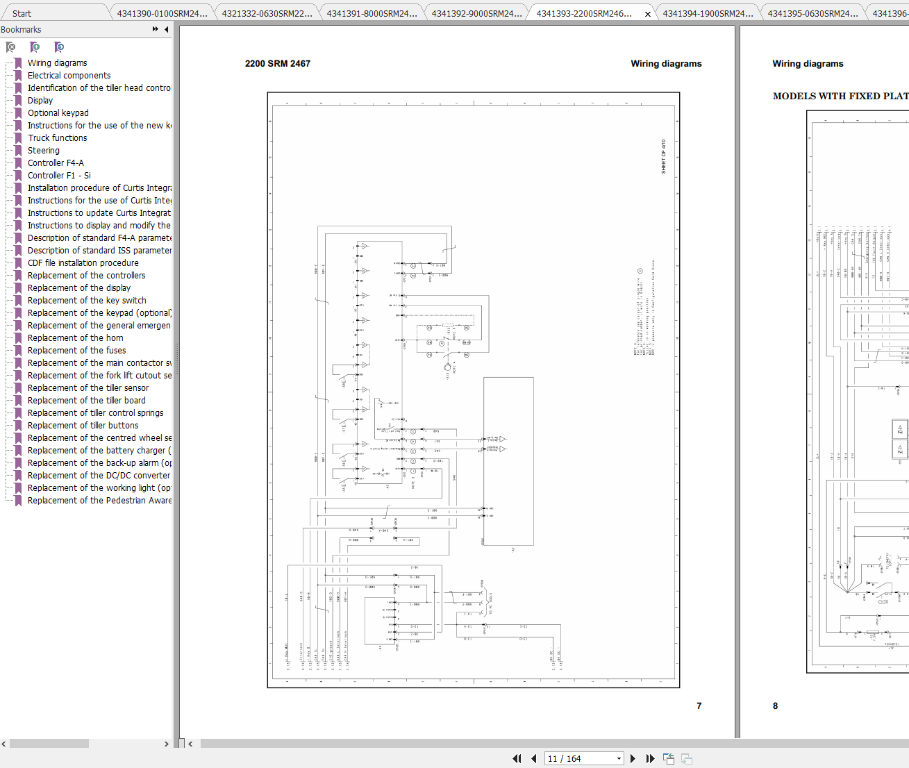
Wiring diagrams
Electrical components
Identification of the tiller head controls and of the operator panel instruments
Display
Optional keypad
Instructions for the use of the new keypad application
Truck functions
Steering
Controller F4-A
Controller F1 - Si
Installation procedure of Curtis Integrated Toolkit
Instructions for the use of Curtis Integrated Toolkit Software
Instructions to update Curtis Integrated Toolkit Software
Instructions to display and modify the parameters
Description of standard F4-A parameters
Description of standard ISS parameters
CDF file installation procedure
Replacement of the controllers
Replacement of the display
Replacement of the key switch
Replacement of the keypad (optional)
Replacement of the general emergency switch
Replacement of the horn
Replacement of the fuses
Replacement of the main contactor switch
Replacement of the fork lift cutout sensor
Replacement of the tiller sensor
Replacement of the tiller board
Replacement of tiller control springs
Replacement of tiller buttons
Replacement of the centred wheel sensor
Replacement of the battery charger (optional)
Replacement of the back-up alarm (optional)
Replacement of the DC/DC converter (optional)
Replacement of the working light (optional)
Replacement of the Pedestrian Awareness Light (optional)
Hydraulic functions
Hydraulic diagrams
Hydraulic diagrams for various functions
Hydraulic components
Dismantling of cartridge soilenoid valves
Removal of the initial lift cylinder
Removal of the cylinder head bushing
Hydraulic power unit removal
Hydraulic power unit disassembly
Identification of the master drive unit
Removal and disassembly of the reduction unit
Removal and replacement of the master drive unit assembly component
Braking System
Removal of the electromagnetic brake
Maintenance Warnings
Oils and Lubricants
Cleaning products
Scheduled Maintenance

Size: 56.6 MB
Format: PDF
Language: English
Brand: Hyster
Model: Hyster A3D9 P2.0S, P2.5S, P3.0S EU Service Manual 03.2022
Type of machine: Forklift Truck
Type of document: Service Manual
Content:
Important
General safety rules
Torque settings for screws nuts and fittings
Correct method for applying female fittings
Instruction for installing flexible hoses and fittings
Truck presentation
Views of the truck
Truck and load identification data
General specification
Traction wheel
Removal of the traction wheel
Torsion bar castor wheel assembly
Torsion bar castor wheel group disassembly
Replacement of the castor wheel torsion bar springs
Replacing the castor wheel
Replacing the castor wheel group
Load wheels
Replacing the tandem load wheel
Replacing the tandem load wheel assembly
Fixed linkage
Adjustable linkage
Removal of the linkage assembly
Key to tiller components
Tiller spring replacement
Adjustable steering spring replacement
Tiller removal
Replacement of the potentiometer and tiller base bearings
Replacement of the potentiometer and tiller base bearings of the adjustable steering
Key to scooter components
Scooter head removal
Scooter spring replacement
Replacement of the scooter control sensor and base bearings
Side gate replacement
Side gates microswitch replacement
Removal of the platform gas spring
Replacement of the platform touchless sensor
Removal of the platform
Replacement of the platform sensor
Traction motor
Motor dismantling
Steering motor
Steering motor dismantling
Forks chassis removal
Removal of the reduction unit
Disassembly of the reduction unit
Braking System
Removal of the electromagnetic brake
Before Installation
Truck assembly
Topping up the oil reservoir
Installation of the battery with vertical extraction
Installation of the battery with lateral extraction
Connection of cables to battery
List and description of the settings and adjustments to be carried out
Description of controller connectors
Device properties
Monitor menu
Troubleshooting
Warnings
Diagnosis system for F4-A Controller
Diagnosis system for Integrated Steering System
Electrical component measurements
Wiring diagrams
Electrical components
Identification of the tiller head controls and of the operator panel instruments
Display
Optional keypad
Instructions for the use of the new keypad application
Truck functions
Steering
Controller F4-A
Controller F1 - Si
Installation procedure of Curtis Integrated Toolkit
Instructions for the use of Curtis Integrated Toolkit Software
Instructions to update Curtis Integrated Toolkit Software
Instructions to display and modify the parameters
Description of standard F4-A parameters
Description of standard ISS parameters
CDF file installation procedure
Replacement of the controllers
Replacement of the display
Replacement of the key switch
Replacement of the keypad (optional)
Replacement of the general emergency switch
Replacement of the horn
Replacement of the fuses
Replacement of the main contactor switch
Replacement of the fork lift cutout sensor
Replacement of the tiller sensor
Replacement of the tiller board
Replacement of tiller control springs
Replacement of tiller buttons
Replacement of the centred wheel sensor
Replacement of the battery charger (optional)
Replacement of the back-up alarm (optional)
Replacement of the DC/DC converter (optional)
Replacement of the working light (optional)
Replacement of the Pedestrian Awareness Light (optional)
Hydraulic functions
Hydraulic diagrams
Hydraulic diagrams for various functions
Hydraulic components
Dismantling of cartridge soilenoid valves
Removal of the initial lift cylinder
Removal of the cylinder head bushing
Hydraulic power unit removal
Hydraulic power unit disassembly
Identification of the master drive unit
Removal and disassembly of the reduction unit
Removal and replacement of the master drive unit assembly component
Braking System
Removal of the electromagnetic brake
Maintenance Warnings
Oils and Lubricants
Cleaning products
Scheduled Maintenance
More the random threads same category:
- Hyster Forklift Parts and Service Manual CD7
- Hyster Forklift Parts and Service Manual CD2
- Hyster Forklift Parts and Service Manual CD3
- Hyster Forklift Diagrams and Schematics
- Hyster Forklift Parts and Service Manual CD4
- Hyster Forklift Parts and Service Manual CD10
- Hyster Forklift Parts and Service Manual CD1
- Hyster Forklift Parts and Service Manual CD9
- HYSTER Forklift H4.0 Shop Manual
- Hyster Forklift Parts and Service Manual CD6
- Hyster THREE-SPEED POWERSHIFT TRANSMISSION REPAIR Manual
- Hyster Forklift Parts and Service Manual CD5
- Hyster Forklift Parts and Service Manual CD8
- Linde Forklift 353-02D Operator Manual , SAFETY TIPS,Electric and Hydraulic circuit diagram
- Perkins Diesel Engines 1004-42(AR) 1006-60(YG) 1006-60T(YH) Repair And Maintenance Manual