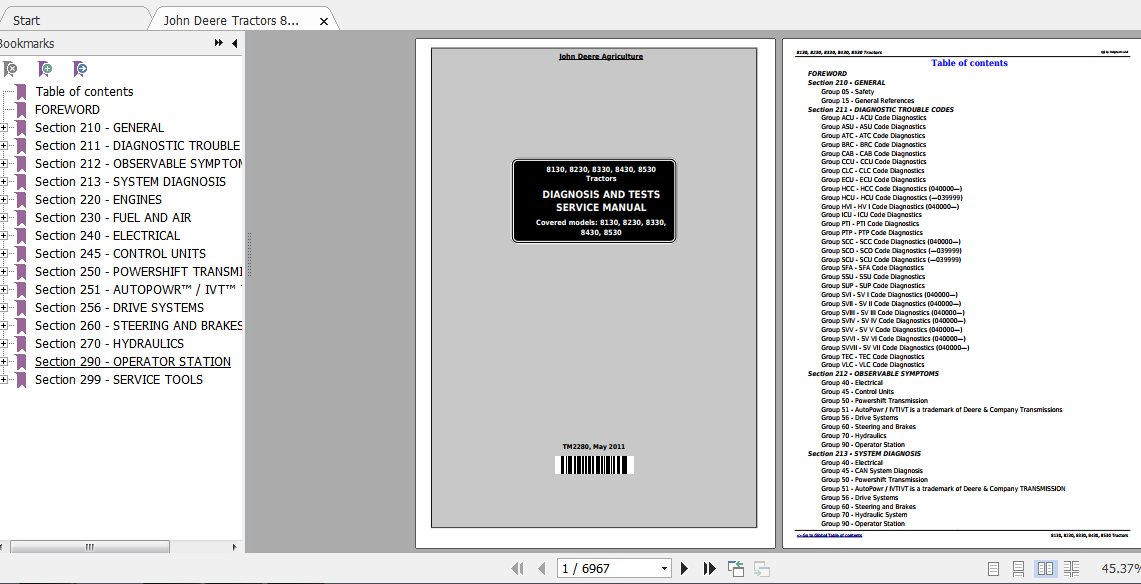
John Deere Tractors 8130 8230 8330 8430 8530 Diagnosis and Tests Service Manual TM2280
- Download this document, you need 6500 Gallons
John Deere 8130 8230 8330 8430 8530 Tractors Diagnosis and Test Service Manual TM2280
Size: 177,7 MB
Format: PDF
Language: English
Type of Document: Service Manual
Type of Machine: Tractor
Model: John Deere Side Shift Loader 325J Diagnostic Test Manual, Service Manual
Number of pages: 6967 pages
Part No: TM2280
Date: May 2011
Detail Content:
Content:
Foreword
GENERAL
Safety
General References
DIAGNOSTIC TROUBLE CODES
ACU Code Diagnostics
ASU Code Diagnostics
ATC Code Diagnostics
BRC Code Diagnostics
CAB Code Diagnostics
CCU Code Diagnostics
CLC Code Diagnostics
ECU Code Diagnostics
HCC Code Diagnostics (040000-)
HCU Code Diagnostics (-039999)
HV I Code Diagnostics (040000-)
ICU Code Diagnostics
PTI Code Diagnostics
PTP Code Diagnostics
SCC Code Diagnostics (040000-)
SCO Code Diagnostics (-039999)
SCU Code Diagnostics (-039999)
SFA Code Diagnostics
SSU Code Diagnostics
SUP Code Diagnostics
SV I Code Diagnostics (040000-)
SV II Code Diagnostics (040000-)
SV III Code Diagnostics (040000-)
SV IV Code Diagnostics (040000-)
SV V Code Diagnostics (040000-)
SV VI Code Diagnostics (040000-)
SV VII Code Diagnostics (040000-)
TEC Code Diagnostics
VLC Code Diagnostics
OBSERVABLE SYMPTOMS
Electrical
Control Units
Powershift Transmission
AutoPowr / IVTIVT is a trademark of Deere & Company
Transmissions
Drive Systems
Steering and Brakes
Hydraulics
Operator Station
SYSTEM DIAGNOSIS
Electrical
CAN System Diagnosis
Powershift Transmission
AutoPowr / IVTIVT is a trademark of Deere & Company
TRANSMISSION
Drive Systems
Steering and Brakes
Hydraulic System
Operator Station
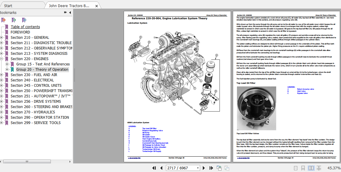
ENGINES
Test And References
Theory of Operation
FUEL AND AIR
Fuel and Air Theory of Operation
ELECTRICAL
Load Center Fuses and Relays
Operational Checks
Functional Schematics
Connector Information
Harness Information
SE01 – Power Supply, Starting and Charging Circuits
SE02 – Manual Seat
SE03 – Manual AC and ATC
SE04 – Remote Mirror Option
SE05 – Radio, Dome Lamp and Multi-Function Switch
SE06 – Cab Load Center / Tractor Equipment Control and Lighting
SE07 – Accessory Connectors
SE08 – CAN Termination
SE09 – Corner Post Display, ICU – Information Display, and SCV
– Setup Panel Display
SE10 – CAB Control Unit / Active Seat Unit (ASU)
SE11 – Power Train / Vehicle Load Center (VLC) and Chassis Control
Unit (CCU)
SE13 – ACU – Armrest Control Unit
SE14 – SCU/HCU/BRC/SFA – Deluxe Hydraulic Control Unit Function
SE14 CAN – SCC/HCC – Deluxe Hydraulic CAN Control Unit Function
SE15 – SCO – Secondary Hydraulic Control Unit Functions
SE16 – ECU Level 14
SE17-JDLINK
SE18-Greenstar Display
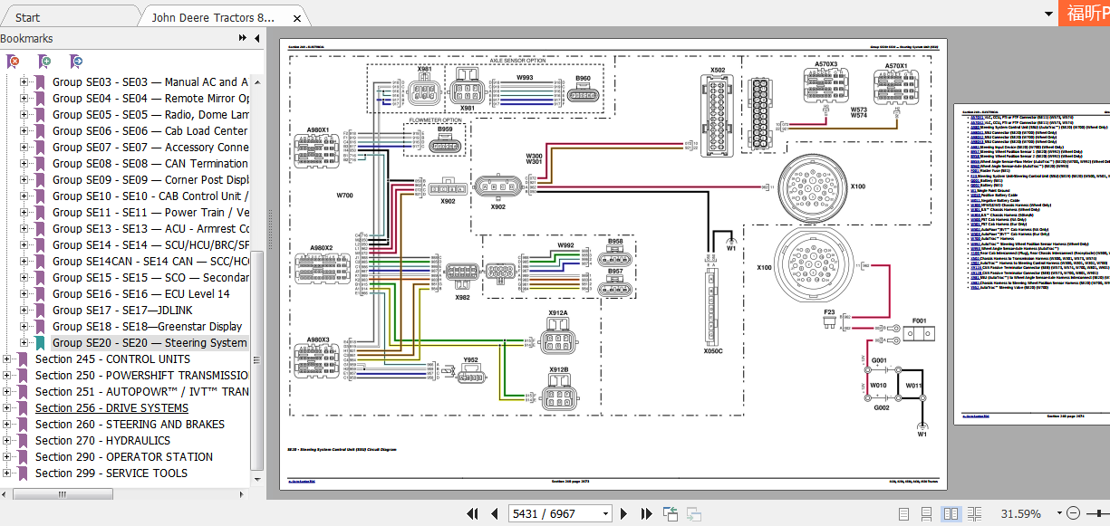
SE20 – Steering System Unit (SSU)
CONTROL UNITS
General References
ACU
ASU
ATC
BRC
CAB
CCU
CLC
ECU
HCC (040000-)
HCU (-039999)
HV I (040000-)
ICU
PTI
PTP
SCC (040000-)
SCO (-039999)
SCU (-039999)
SFA
SSU
SUP
SV I – VII (040000-)
TEC
VLC
POWERSHIFT TRANSMISSION
Preliminary Checks
Operational Checks
Tests and Adjustments
Theory of Operation
Schematics and Diagrams
AUTOPOWR™ / IVT™ TRANSMISSION
Preliminary Checks
Operational Checks
Test And Adjustments
Theory of Operation
Schematics and Diagrams
DRIVE SYSTEMS
Preliminary Checks
Operational Checks
Tests and Adjustments
Theory of Operation
Schematics and Diagrams
STEERING AND BRAKES
Preliminary Checks
Operational Checks
Tests and Adjustments
Theory of Operation
Schematics and Diagrams
HYDRAULICS
Preliminary Checks
Operational Checks
Tests and Adjustments
Theory Of Operation
Schematics and Diagrams
OPERATOR STATION
Preliminary Checks
Operational Checks
Tests and Adjustments
Theory Of Operation
Schematics and Diagrams
SERVICE TOOLS
Dealer Fabricated Tools
Service Tools and Kits

Size: 177,7 MB
Format: PDF
Language: English
Type of Document: Service Manual
Type of Machine: Tractor
Model: John Deere Side Shift Loader 325J Diagnostic Test Manual, Service Manual
Number of pages: 6967 pages
Part No: TM2280
Date: May 2011
Detail Content:
Content:
Foreword
GENERAL
Safety
General References
DIAGNOSTIC TROUBLE CODES
ACU Code Diagnostics
ASU Code Diagnostics
ATC Code Diagnostics
BRC Code Diagnostics
CAB Code Diagnostics
CCU Code Diagnostics
CLC Code Diagnostics
ECU Code Diagnostics
HCC Code Diagnostics (040000-)
HCU Code Diagnostics (-039999)
HV I Code Diagnostics (040000-)
ICU Code Diagnostics
PTI Code Diagnostics
PTP Code Diagnostics
SCC Code Diagnostics (040000-)
SCO Code Diagnostics (-039999)
SCU Code Diagnostics (-039999)
SFA Code Diagnostics
SSU Code Diagnostics
SUP Code Diagnostics
SV I Code Diagnostics (040000-)
SV II Code Diagnostics (040000-)
SV III Code Diagnostics (040000-)
SV IV Code Diagnostics (040000-)
SV V Code Diagnostics (040000-)
SV VI Code Diagnostics (040000-)
SV VII Code Diagnostics (040000-)
TEC Code Diagnostics
VLC Code Diagnostics
OBSERVABLE SYMPTOMS
Electrical
Control Units
Powershift Transmission
AutoPowr / IVTIVT is a trademark of Deere & Company
Transmissions
Drive Systems
Steering and Brakes
Hydraulics
Operator Station
SYSTEM DIAGNOSIS
Electrical
CAN System Diagnosis
Powershift Transmission
AutoPowr / IVTIVT is a trademark of Deere & Company
TRANSMISSION
Drive Systems
Steering and Brakes
Hydraulic System
Operator Station
ENGINES
Test And References
Theory of Operation
FUEL AND AIR
Fuel and Air Theory of Operation
ELECTRICAL
Load Center Fuses and Relays
Operational Checks
Functional Schematics
Connector Information
Harness Information
SE01 – Power Supply, Starting and Charging Circuits
SE02 – Manual Seat
SE03 – Manual AC and ATC
SE04 – Remote Mirror Option
SE05 – Radio, Dome Lamp and Multi-Function Switch
SE06 – Cab Load Center / Tractor Equipment Control and Lighting
SE07 – Accessory Connectors
SE08 – CAN Termination
SE09 – Corner Post Display, ICU – Information Display, and SCV
– Setup Panel Display
SE10 – CAB Control Unit / Active Seat Unit (ASU)
SE11 – Power Train / Vehicle Load Center (VLC) and Chassis Control
Unit (CCU)
SE13 – ACU – Armrest Control Unit
SE14 – SCU/HCU/BRC/SFA – Deluxe Hydraulic Control Unit Function
SE14 CAN – SCC/HCC – Deluxe Hydraulic CAN Control Unit Function
SE15 – SCO – Secondary Hydraulic Control Unit Functions
SE16 – ECU Level 14
SE17-JDLINK
SE18-Greenstar Display
SE20 – Steering System Unit (SSU)
CONTROL UNITS
General References
ACU
ASU
ATC
BRC
CAB
CCU
CLC
ECU
HCC (040000-)
HCU (-039999)
HV I (040000-)
ICU
PTI
PTP
SCC (040000-)
SCO (-039999)
SCU (-039999)
SFA
SSU
SUP
SV I – VII (040000-)
TEC
VLC
POWERSHIFT TRANSMISSION
Preliminary Checks
Operational Checks
Tests and Adjustments
Theory of Operation
Schematics and Diagrams
AUTOPOWR™ / IVT™ TRANSMISSION
Preliminary Checks
Operational Checks
Test And Adjustments
Theory of Operation
Schematics and Diagrams
DRIVE SYSTEMS
Preliminary Checks
Operational Checks
Tests and Adjustments
Theory of Operation
Schematics and Diagrams
STEERING AND BRAKES
Preliminary Checks
Operational Checks
Tests and Adjustments
Theory of Operation
Schematics and Diagrams
HYDRAULICS
Preliminary Checks
Operational Checks
Tests and Adjustments
Theory Of Operation
Schematics and Diagrams
OPERATOR STATION
Preliminary Checks
Operational Checks
Tests and Adjustments
Theory Of Operation
Schematics and Diagrams
SERVICE TOOLS
Dealer Fabricated Tools
Service Tools and Kits
More the random threads same category:
- JOHN DEERE JD-410 Technical Manual
- Funk Power DF Series 150 & 250 Transmission Service Manual
- John Deere Service ADVISOR 4.0 CF+JDIN+History Data (11.2013)
- John Deere Parts Manager Pro 6.5.5 (CF) Construction & Foresty [03.2016]
- John Deere Service Advisor 4.1.011 + 4 dvd data RU (01.2013)
- John Deere 750C,850C Crawler Dozer Technical Manual
- John Deere Service Advisor 4.01.11
- John Deere 750J,850J Crawler Dozer Parts Catalog
- John Deere 6020 Series Repair Manuals (6020 to 6920S)
- John Deere Service Advisor 4.1.007 Torrent 28.11.2013
- Jonh Dree 690E LC Excavator Techical Manual
- John Deere 700J Crawler Dozer Parts Catalog
- John Deere 850J Crawler Dozer Tier 3 Parts Catalog
- John Deere LTR155, LTR166 and LTR180 Lawn Tractors Technical manual
- JOHN DEERE CODE DTC LIST